


I wanted the switches of a real race car cockpit at hand when driving the GT3 and GTP cars in iRacing: ignition and starter, pit limiter, the pit-stop options, brake bias, traction control and ABS. So I designed and built this button box: a Teensy 4.1 board, 25 controls, a 3D-printed case and a rigid bracket for the aluminium profile of the rig. The PC sees it as a normal USB keyboard, with no drivers.
This article is the complete guide to building it yourself, from the shopping list to your first lap, with all the photos, diagrams and step-by-step checks. No electronics experience is needed: just some patience and the will to learn to solder.
Print files on MakerWorldFirmware v2.6 (.zip)
Contents
- The box at a glance
- How it works (in plain words)
- Before you start: skills, time, tools
- Shopping list
- Print the case and the bracket
- Build the main board
- Make the cables for the controls
- Test 1 — multimeter check of the bare board
- Install the firmware
- Test 2 — bare board with a jumper wire
- Assemble the box
- Test 3 — the complete box
- Mount the box on the rig
- Set up iRacing
- Adapt the firmware to your box
- Troubleshooting
- Appendix A — Soldering basics
- Appendix B — Reference tables and diagrams
- Appendix C — Serial Monitor messages
- Appendix D — Glossary
About this guide
This guide explains, one step at a time, how to build the button box shown in the photos: what to buy, how to print the case, how to solder and wire it, how to load the program, how to test it and how to set it up in iRacing. It is written for people who have never built electronics before. If you can follow a recipe and you are willing to learn to solder, you can build this box.
How to read this guide
- Chapters 1–3 explain what the box does and how it works. Read them once, even if you are in a hurry: they make the rest much easier.
- Chapters 4–14 are the build steps, in the order you should do them. Each one ends with a check. Do not skip the checks: a mistake found early takes minutes to fix, the same mistake found in a closed box takes hours.
- Chapter 15 shows how to adapt the firmware to your own layout, Chapter 16 is for troubleshooting. The appendices hold reference tables, soldering basics and a glossary.
Blue boxes give background and tips, orange boxes warn about common mistakes, red boxes flag a risk of damage or injury.
Safety
- A soldering iron tip is at 300–380 °C. Always put it back in its stand, work in a ventilated room and wear safety glasses when you cut wires or use desoldering braid.
- Most solder wire contains lead. Do not eat or touch your face while soldering, and wash your hands afterwards.
- The box is powered only by the 5 V of a USB port, which is safe to touch. The protections described in this guide (fuse, power switch) are there to protect your PC and the Teensy board, not you — but please do not skip them.
- Never connect or disconnect cables inside the box while it is plugged into the PC.
License and disclaimer
The text of this guide, the photos, the diagrams and the firmware are released under the Creative Commons Attribution-NonCommercial-ShareAlike 4.0 International license (CC BY-NC-SA 4.0): you may copy, share and modify them for non-commercial purposes, as long as you credit the author and share your changes under the same license. The 3D models (the button box and the iRacing overlay) are available exclusively on MakerWorld, under the MakerWorld Exclusive License: you may publish modified versions only on MakerWorld, crediting the author; you may not republish them on other platforms or use them commercially.
Product names (iRacing, Teensy, Fanatec, Bambu Lab, Arduino and others) belong to their owners and are used only to identify compatible products. This project is not affiliated with any of them. The box is a hobby project, provided “as is”, without any warranty: you build and use it at your own risk.
1. The box at a glance
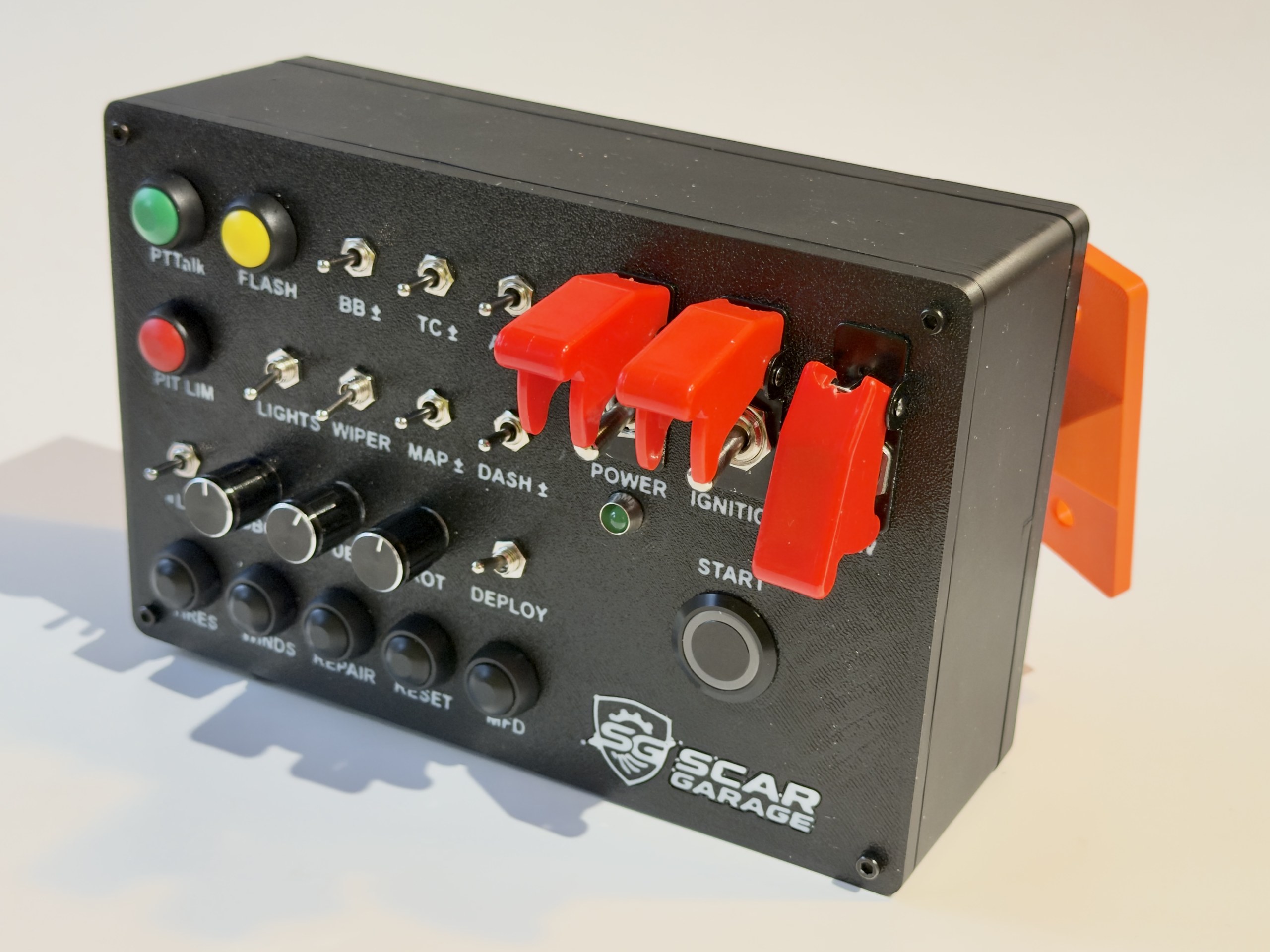
A button box adds the switches and knobs of a real race car cockpit to your sim rig. This one was designed for GT3 and GTP (hybrid) cars in iRacing, next to a Fanatec ClubSport Formula V2.5 wheel, but it works with any simulator that lets you assign keyboard keys or joystick buttons.

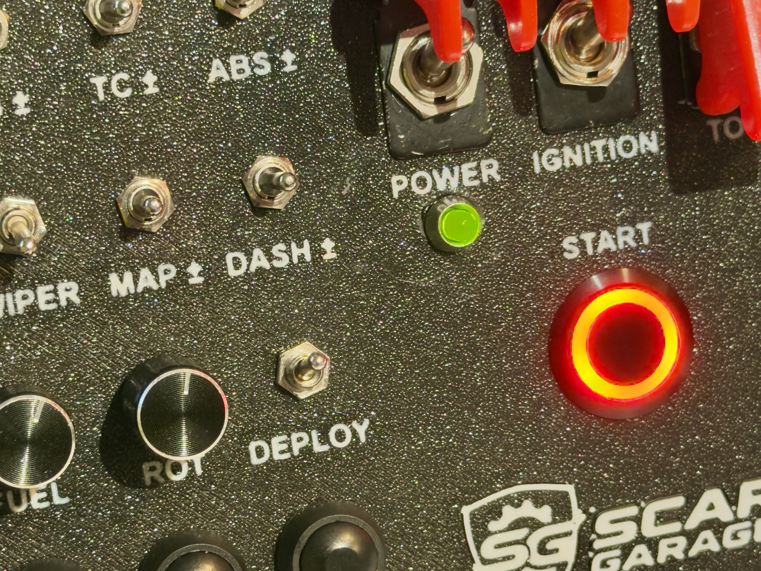
Main features
| Feature | Details |
|---|---|
| Controls | 25 panel holes: 8 push buttons, 6 spring-return toggles (+/−), 3 on/off toggles, 3 toggles with a red safety cover, 3 rotary knobs (encoders), 1 illuminated START button, 1 power LED |
| Inputs | 32 electrical contacts read by a Teensy 4.1 board, plus 1 output (the START lamp) |
| How the PC sees it | As a standard USB keyboard (each control sends Ctrl+Shift+a key) plus a joystick with one button (DEPLOY). No driver, no extra software. |
| Power | One USB-C cable to the PC. Inside: a resettable fuse (0.5 A) and a POWER switch. Consumption about 110–170 mA. |
| Electronics | Perfboard 10 × 15 cm, point-to-point wiring. Every control plugs into its own connector, so any part can be replaced without desoldering the others. |
| Case | 3D-printed in three parts (case, bottom, top plate with or without labels), 208 × 134 × 60 mm |
| Mounting | Rigid printed bracket for a 40 × 80 aluminium profile (two M8 T-nuts), VESA 75 × 75 pattern on the box. Left-hand and right-hand versions. |
Panel layout
Front view. Each cell shows the label printed on the panel and the type of control.
| PTTalk button |
FLASH button |
BB ± toggle ± |
TC ± toggle ± |
ABS ± toggle ± |
POWER covered |
IGNITION covered |
TOW covered |
|
| PIT LIM button |
LIGHTS on/off |
WIPER on/off |
MAP ± toggle ± |
DASH ± toggle ± |
● power LED |
|||
| ◄L/R► toggle, horizontal |
BBOX knob |
FUEL knob |
ROT knob |
DEPLOY on/off |
START lit button |
|||
| TIRES button |
WINDS button |
REPAIR button |
RESET button |
MFD button |
Colours: white = push button · lilac = toggle switch · blue = rotary encoder · pink = covered toggle / START.
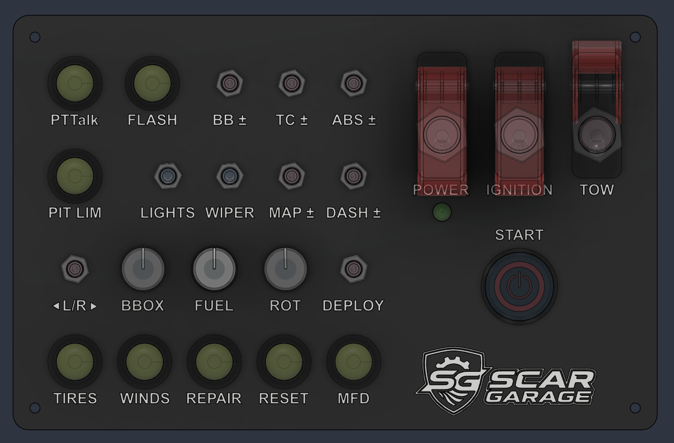
What each control does
All keys are sent together with Ctrl+Shift. For example PIT LIM sends Ctrl+Shift+Q. The last column is the iRacing function the author assigns to it; you can assign anything you like. Chapter 14 gives the exact iRacing functions and the chat macros.
| Label | Control | Action | Key | Behaviour | Suggested iRacing function |
|---|---|---|---|---|---|
| PTTalk | button | press | P |
held while pressed | Push-to-talk |
| FLASH | button | press | F |
held while pressed | Headlight flash |
| BB ± | toggle ± | up / down | B / N |
one pulse per flick | Brake bias + / − |
| TC ± | toggle ± | up / down | T / Y |
one pulse per flick | Traction control + / − |
| ABS ± | toggle ± | up / down | A / S |
one pulse per flick | ABS + / − |
| MAP ± | toggle ± | up / down | M / K |
one pulse per flick | Engine map + / − |
| DASH ± | toggle ± | up / down | D / E |
one pulse per flick | Dash page + / − |
| ◄L/R► | toggle ±, horizontal | left / right | L / F11 |
one pulse per flick | Chat message “passing left / right” (macro) |
| PIT LIM | button | press | Q |
one pulse | Pit limiter |
| LIGHTS | on/off toggle | every change | F6 |
one pulse up and down | Headlights |
| WIPER | on/off toggle | every change | F7 |
one pulse up and down | Wipers |
| BBOX | knob | clockwise / counter-cw | O / I |
one pulse per click | Next / previous black box |
| FUEL | knob | clockwise / counter-cw | U / J |
one pulse per click | Pit fuel +1 / −1 litre (macro) |
| ROT | knob | clockwise / counter-cw | G / H |
one pulse per click | Change the selected black box control + / − |
| DEPLOY | on/off toggle | lever up | joystick button 1 |
held while lever is up | Hybrid deploy (GTP) |
| TIRES | button | press | F1 |
one pulse | Pit: tyre change on / off (macro) |
| WINDS | button | press | F2 |
one pulse | Pit: windscreen tear-off (macro) |
| REPAIR | button | press | F3 |
one pulse | Pit: fast repair (macro) |
| RESET | button | press | F4 |
one pulse | Pit: clear all options (macro) |
| MFD | button | press | F5 |
one pulse | Next control of the black box |
| IGNITION | covered toggle | up / down | F8 |
one pulse at once when raised; one pulse 2 s after lowering | Ignition |
| START | lit button | press | F10 |
held, only with IGNITION ON | Starter |
| TOW | covered toggle | every flick, up or down | F9 |
held 5 s; a second flick within 5 s cancels | Tow to pits |
| POWER | covered toggle | — | — | switches the box on and off | — |
- Ignition works like a car key. In iRacing every ignition “press” switches the ignition on or off, while a toggle stays where you leave it. So the box sends one pulse as soon as you raise the lever (ignition on) and one pulse when the lever has stayed down for 2 seconds (engine off). Down and up again within 2 seconds (a quick flick) sends a single pulse, on the way up: use it after a reset or a return to the garage, when the lever is still up but the car is off.
- Start works only with IGNITION up, and the red lamp in the START button lights when IGNITION is up: the sequence POWER → IGNITION → START is the same as in a real car.
- Tow: iRacing asks you to hold the key for at least 4 seconds; the box holds it for 5 seconds for you. What counts is the flick, not the position, so the lever never gets out of step with the car.
- Deploy may stay active for minutes: a joystick button is better than a keyboard key, which would repeat and keep Ctrl+Shift pressed for all the other keys.
2. How it works (in plain words)
Every control is just a contact to ground
A switch or a button is simply a contact that is open or closed. Each control has one wire to a pin of the Teensy board and one wire to GND (ground, the 0 V “return” wire). Inside the Teensy, a tiny resistor (called pull-up) keeps every pin at 3.3 V. When you press the button, the contact connects the pin to GND and the voltage drops to 0 V. The program sees this change and sends the matching keyboard shortcut to the PC.
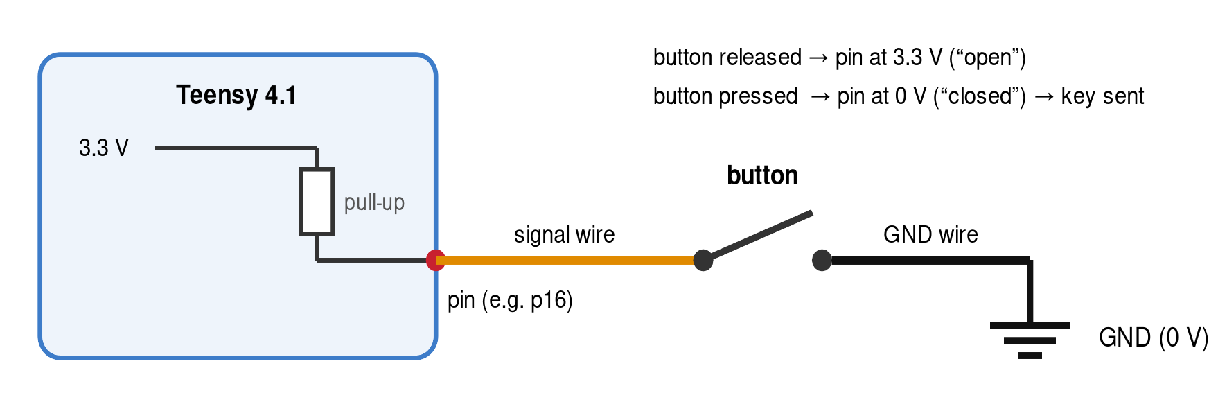
Some controls have two contacts and therefore two signal wires plus GND:
- Spring-return toggles (+/−): one contact closes when you push the lever up, the other when you push it down. In the middle position both are open.
- Rotary encoders (knobs): two contacts (A and B) open and close in a sequence when you turn the knob. From the order of the sequence the program knows the direction. One “click” of the knob produces 4 changes and the program sends one key.
Why a keyboard with Ctrl+Shift?
The Teensy can pretend to be a USB keyboard and a joystick at the same time. Using a keyboard has three advantages: there is no limit of 32 buttons as with many joystick drivers; the key codes are the same on every keyboard layout (English, Italian, German…); adding Ctrl+Shift makes conflicts with the simulator’s default keys unlikely. The digits 1…0 are left free because iRacing uses them for chat macros.
The box sends Ctrl+Shift the way a person types them: first Ctrl+Shift alone, then, 20 ms later, the key; on release the key goes first and Ctrl+Shift follow 20 ms later. This matters when you assign the functions: iRacing records the whole combination (for example CTRL+SHIFT+T), so you can assign every function by simply operating the box.
The parts inside the box
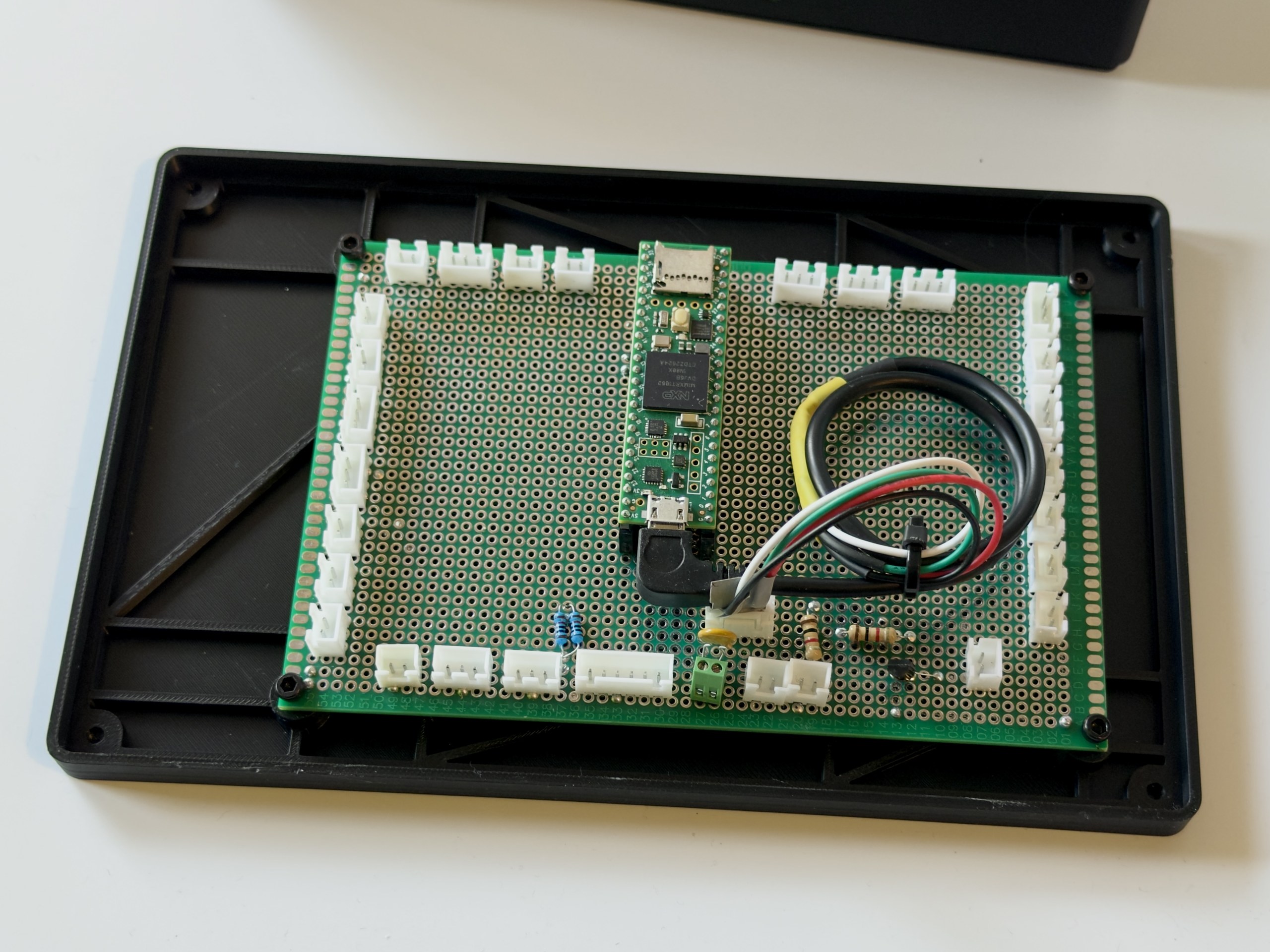
| Part | Role |
|---|---|
| Teensy 4.1 | Small computer board that reads the controls and talks to the PC. It plugs into two sockets, so it can be removed without desoldering. |
| Perfboard (main board) | Board full of holes on which the sockets, the connectors and a few small parts are soldered, joined by thin wires underneath. |
| JST-XH connectors | Small white plugs, one for each control. Each cable goes from a control on the panel to its connector on the board. |
| USB-C socket | On the side of the case. Its 5 wires go to the board, and from the board a short micro-USB cable (“pigtail”) feeds the Teensy. |
| PTC fuse, POWER switch | The fuse protects the PC’s USB port in case of a short circuit and resets itself. POWER cuts the 5 V supply. |
| Transistor + resistors | Switch on the lamp of the START button (the Teensy pins are too weak to drive it directly). |
3. Before you start: skills, time, tools
Skills
| Skill | Level needed |
|---|---|
| 3D printing | Basic. Access to a printer with a bed of at least 210 × 140 mm (or a print service). PETG experience helps. |
| Soldering | Beginner. There is no fine-pitch soldering: all joints are on 2.54 mm pitch holes or on large terminals. Appendix A teaches the technique. Practise on a spare piece of perfboard first. |
| Crimping | Beginner. You will crimp about 70 small JST-XH contacts: after the first ten it becomes routine (Chapter 7). |
| Computer | Install a program (Arduino IDE), open a file, click Upload. No programming is required. |
| Multimeter | Continuity test (beep) and DC voltage. Both are explained where they are used. |
Time
| Phase | Rough time |
|---|---|
| Ordering parts (mostly Amazon, four parts from AliExpress) | a few days for Amazon, 2–3 weeks for AliExpress |
| 3D printing (4 plates) | 1–2 days of printer time |
| Perfboard (sockets, connectors, 46 wires, ground ring) | 2–3 evenings |
| Cables for the 25 controls | 2 evenings |
| Firmware, tests, assembly, iRacing setup | 1–2 evenings |
Tools
| Tool | Used for |
|---|---|
| Temperature-controlled soldering iron, fine conical or small chisel tip, brass tip cleaner | All soldering |
| Solder wire 0.6–0.8 mm with flux core, flux paste, desoldering braid | All soldering and corrections |
| Multimeter with continuity buzzer | Checking every wire and the power supply |
| Crimping pliers SN-01BM (or equivalent for JST-XH) — Amazon (SN-01BM) · AliExpress | JST-XH contacts (2.5 mm pitch connectors) |
| Crimping pliers SN-02C with die SN-06WF (or equivalent) — Amazon · AliExpress | 2.8 mm faston terminals and 0.25 mm² ferrules |
| Wire stripper for thin wires (26–28 AWG), flush cutters, small pliers, tweezers | Wire preparation |
| Heat gun or lighter | Heat-shrink tubing |
| Isopropyl alcohol (90 % or more) and an old toothbrush | Cleaning flux residue |
| Magnifying glass or phone camera | Checking joints for bridges |
| Female-female Dupont jumper wire | Testing the bare board (Chapter 10) |
| Spanners or a socket set for the panel nuts (M6, M7, M12, M22) | Mounting the controls |
| Soldering iron with a heat-set insert tip (or the main iron) | M3 heat-set inserts in the printed parts |
| A PC with Windows, a free USB port and a USB data cable | Firmware and tests |
4. Shopping list
Order everything before you start: most parts come from Amazon in a few days, but four parts are only available on AliExpress and take two to three weeks. The quantities below are for one box. A few spares of the cheap parts are a good idea: a switch can arrive faulty, and a spare lets you replace it at once.
4.1 Panel controls
| Part | Qty | Panel hole | Useful data | Where to buy (variant) |
|---|---|---|---|---|
| PBS-33B push button 12 mm, normally open, momentary | 8 | 12.0 mm | M12 × 0.75 thread, head Ø 17.6 mm, small solder tabs | Amazon (pack of 6, 6 colours: buy 2) · AliExpress |
| MTS-123 toggle (ON)-OFF-(ON), spring return to centre | 6 | 6.0 mm + anti-rotation hole Ø 2.4 mm at 6.4 mm | M6 × 0.75, lever 11 mm, 3 pins; the anti-rotation tab is on the washer | Amazon (pack of 5: buy 2) |
| MTS-101 toggle ON-OFF | 3 | 6.0 mm | M6 × 0.75, 2 pins | Amazon (pack of 5) · AliExpress |
| EC11 rotary encoder with push (push not used) | 3 | 7.2 mm | M7 × 0.75, 20 clicks per turn, 4 transitions per click; knob Ø 15 × 17 mm | Amazon · AliExpress (variant “with 17×15 caps”) — the bare encoder with knob, not the version soldered on a small module board |
| KN3A-101 toggle ON-OFF with flip-up safety cover | 3 | 12.0 mm | M12 × 0.75, screw terminals, body 28 × 16 mm | AliExpress 1005010102336311 — variant “KN3A-101 N cap” (red cover). Not available on Amazon |
| Illuminated push button 22 mm, momentary, red LED ring 3–6 V | 1 | 22.0 mm | M22 × 1, flange Ø 24.8 mm, supplied with wires; LED has a built-in resistor | AliExpress 1005006370536493 — variant “Red Led (1NO) / Alumina (Black) / 3-6V / 22mm (with wires)”. Amazon only has 12–24 V versions, too dim at 5 V |
| LED 5 mm, diffused, any colour | 1 | 5.2 mm | Forward voltage about 2 V | Amazon (assortment kit) · AliExpress |
4.2 Electronics
| Part | Qty | Notes | Where to buy |
|---|---|---|---|
| Teensy 4.1 with pins already soldered | 1 | Buy an original PJRC board: clones may not work with the official software. | Amazon (original PJRC, with pins) or pjrc.com |
| Female socket strip 1 × 24, 2.54 mm pitch | 2 | The Teensy plugs into these and can be removed. | Amazon (1 × 40, cut to 24) · AliExpress |
| Double-sided perfboard 10 × 15 cm | 1 | Must have 55 × 37 holes, 2.54 mm pitch, with printed coordinates. | AliExpress 1005006846901213 — variant “10X15CM”. The coordinates in this guide need exactly this layout (55 × 37 holes, printed coordinates) |
| JST-XH straight PCB headers | 17 × 2-pin 10 × 3-pin 1 × 4-pin 1 × 6-pin |
With matching housings and loose contacts (SXH-001T-P0.6). An assortment kit is the easiest choice. One 3-pin is a spare position (KR). | Amazon (assortment kit) · AliExpress |
| PTC resettable fuse RXEF050 (0.5 A hold) | 1 | Mounted in a small 2-way PCB screw terminal so it can be replaced. | Amazon (pack of 10) · AliExpress |
| 2-way PCB screw terminal, 5 mm or 5.08 mm pitch | 1 | Holds the PTC fuse. | Amazon (pack of 10) · AliExpress |
| Resistor 1 kΩ, ¼ W | 2 | R1 (transistor base), R2 (power LED) | Amazon (assortment kit, also has 10 kΩ) · AliExpress |
| Resistor 10 kΩ, ¼ W | 2 | R3: two in parallel = about 5 kΩ on the USB-C “CC” line | Same kit as 1 kΩ |
| Transistor BC337 (NPN) | 1 | Q1, drives the START lamp | Amazon (assortment kit) · AliExpress |
| Panel-mount USB-C socket with 5 wires and nut | 1 | Wire colours: green CC, black GND, white D−, blue D+, red VBUS | AliExpress 1005012453528943 — variant “5Pin cable” (not “5Pin PH2.0”). The panel sockets on Amazon are power-only (2 wires): the PC would not see the box |
| USB-A to micro-USB data cable with right-angle micro plug | 1 | Cut to 15–20 cm to make the internal “pigtail”. Must be a data cable (4 wires inside), not a charge-only cable. | Amazon (data cable, right-angle plug) · AliExpress |
| USB-C cable to the PC | 1 | USB-A → USB-C or USB-C ↔ USB-C, data capable | Any |
4.3 Wire, terminals, consumables
| Material | Used for | Where to buy |
|---|---|---|
| Silicone wire 26 AWG, 6 colours (black included) | All cables between panel and board | Amazon (6 colours) · AliExpress |
| Solid PTFE-insulated wire 28 AWG, silver-plated, several colours | Point-to-point wiring under the perfboard | Amazon (choose 28 AWG, 5 m; one colour per pack: buy 2–3 colours) · AliExpress |
| Bare tinned copper wire (about 0.5 mm) | Ground ring around the board | Amazon · AliExpress |
| JST-XH crimp contacts SXH-001T-P0.6 | About 70 (plus spares) | Included in the XH kit (Amazon) |
| Insulated female faston 2.8 mm | 24 (toggle switches MTS-123 and MTS-101) | Amazon (pack of 100) · AliExpress |
| Wire-end ferrules 0.25 mm² | 6 (screw terminals of the covered toggles) | Amazon (pack of 100) · AliExpress |
| Heat-shrink tubing Ø 2 mm and Ø 3 mm | Every solder joint on the controls | Amazon (assortment) · AliExpress |
| Kapton tape, small cable ties, hot glue | Tidying and strain relief | Any |
4.4 Mechanical parts
| Part | Qty | Notes |
|---|---|---|
| PETG filament, black (or any colour) + white for the labels | about 0.5 kg | Everything in PETG. Only the top plate with labels needs a second colour; the top without labels is single-colour. Buy: Bambu Lab PETG Basic: black, white |
| M3 heat-set inserts (outer Ø 4.2 mm, length 6 mm) | as in the model | Bottom fixing screws and VESA mount. You need exactly Ø 4.2 × 6 mm, because the holes of the printed parts are sized for them. Buy: Amazon · AliExpress (choose Ø 4.2 × 6 mm) |
| M3 screws | 4 + case screws | 4 for the bracket (VESA 75 × 75); lengths to suit your print Buy: Amazon (assortment) · AliExpress |
| M3 standoffs | 4 | Optional: to lift the perfboard off the bottom Buy: Amazon (assortment) · AliExpress |
| M8 bolts + M8 T-nuts for 40-series aluminium profile | 2 + 2 | Mounting on a 40 × 80 profile (choose bolt length for 5 mm plate + T-nut) Buy: T-nuts: Amazon · AliExpress; M8 × 16 bolts: Amazon · AliExpress |
| M8 large washers DIN 9021 (Ø 24 mm) | 2 | Spread the load on the plastic Buy: Amazon · AliExpress |
5. Print the case and the bracket
The box is made of four printed parts. The case, the bottom and the bracket form a general-purpose frame; all labels are on a thin separate top plate. If you want different labels, you only reprint the top. The project has six build plates, because two parts come in two versions: you print four of them.
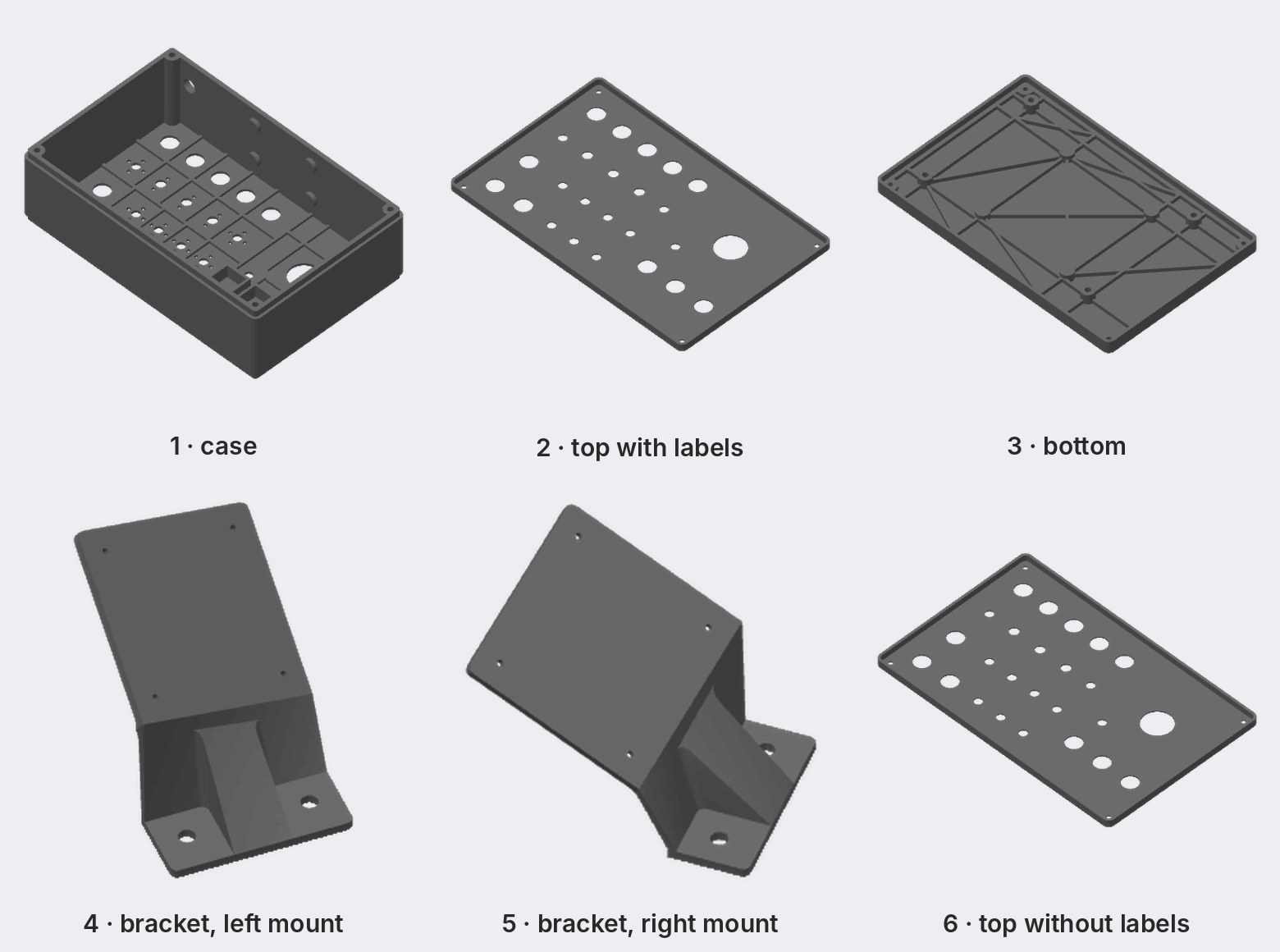
| Part | Size | Role |
|---|---|---|
| case | 208 × 134 × 60 mm, front 2 mm thick | Holds all the controls. The holes have cross-shaped anti-rotation notches, so the toggles can be turned in 90° steps. The USB-C socket goes in the side wall. |
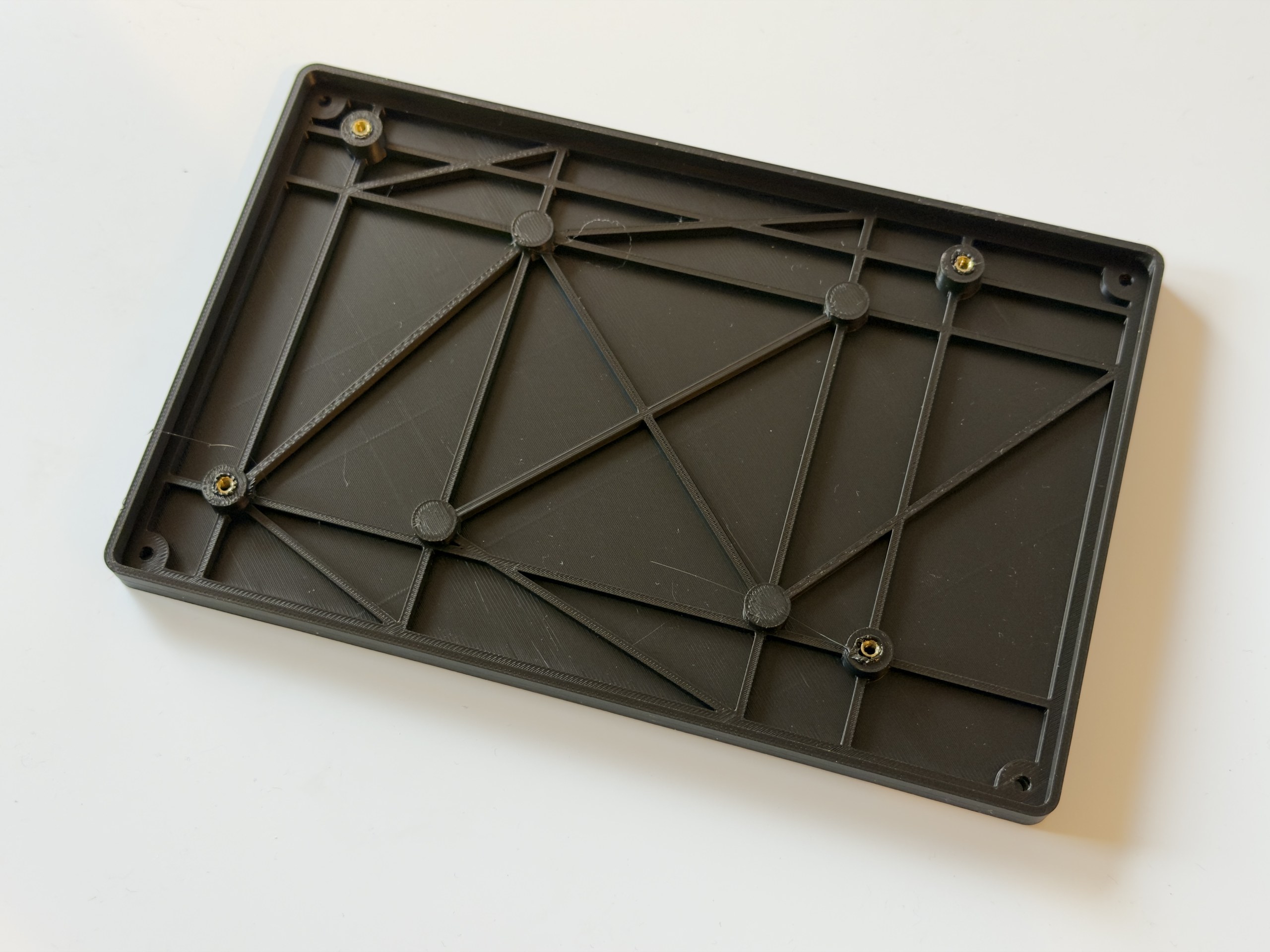
| bottom | 208 × 134 × 10 mm (5 mm fit into the case) | Closes the box. Ribbed, with 8 posts; 4 of them take the VESA 75 bracket screws. |
| top | 208 × 134 mm, 1 mm plate | Clamped against the front by the nuts of the controls. With labels: the layout of this guide, in two colours. Without labels: same holes, one colour, for your own layout and labels (Chapter 15). |
bracket (staffa_l / staffa_r) |
Plate 93 × 40 × 5 mm on the profile; arm 93 mm high | Joins the bottom to the aluminium profile of the rig. Two mirror-image versions: box on the left or on the right of the wheel. |
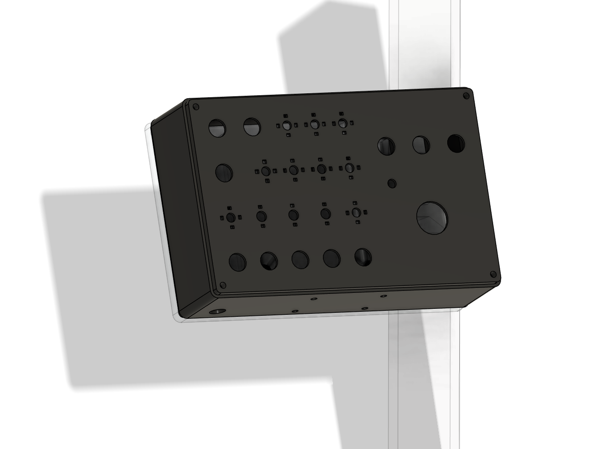
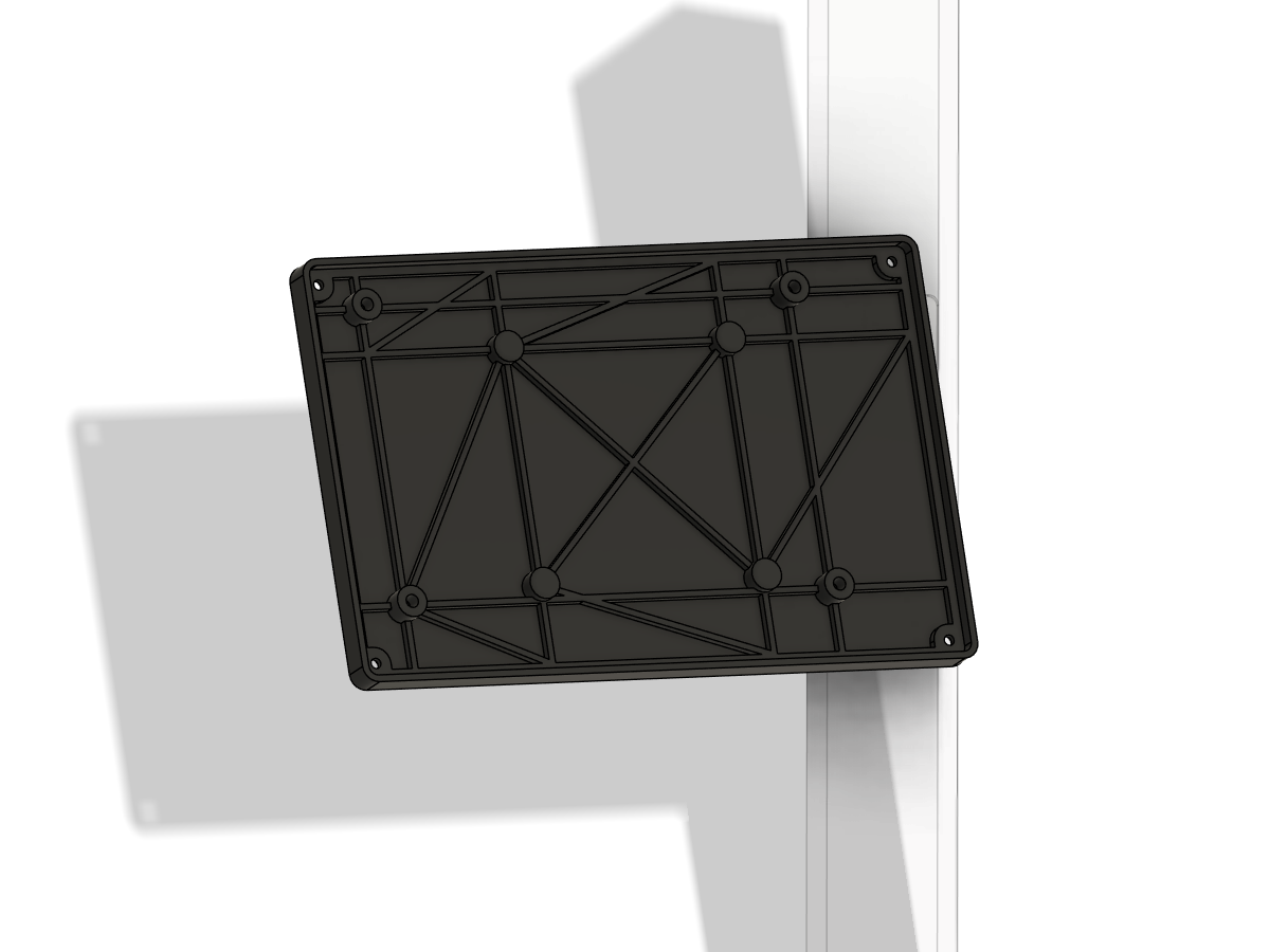
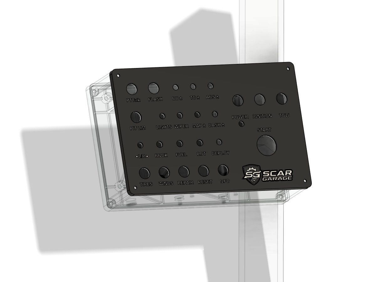
5.1 Print settings
| Setting | Value |
|---|---|
| Printer used | Bambu Lab H2S, 0.4 mm nozzle, profile “0.20 mm High Quality”, textured PEI plate. Any printer with a large enough bed works. |
| Material | PETG for every part (the project is already set up with PETG: filament 1 white, filament 2 black). PLA softens in a hot room or in the sun and creeps under the bracket bolts. |
| Common settings | 2 walls, gyroid infill 15 %, 5 top layers, 3 bottom layers; supports off unless stated below |
| Plate | Part | Own settings | When to print it |
|---|---|---|---|
| 1 | case | Automatic supports | Always |
| 2 | top with labels and logo (black, white labels) | Two colours: AMS / multi-material unit, or print in one colour and paint the raised letters | If you build the layout of this guide |
| 3 | bottom | 3 walls, zig-zag infill, no supports | Always |
| 4 | bracket, left mount (staffa_l) |
5 walls, outer brim 15 mm | Box on the left of the wheel (as in the photos) |
| 5 | bracket, right mount (staffa_r) |
5 walls, outer brim 15 mm | Box on the right of the wheel |
| 6 | top without labels | One colour | Instead of plate 2, for your own layout |
5.2 After printing
- Remove supports and brim. Clean the holes with a deburring tool.
- Press the M3 heat-set inserts into the bottom posts with the soldering iron (about 220–240 °C for PETG), keeping them straight. Let them cool before screwing.
- Lay the top on the case and check that all 25 holes line up.
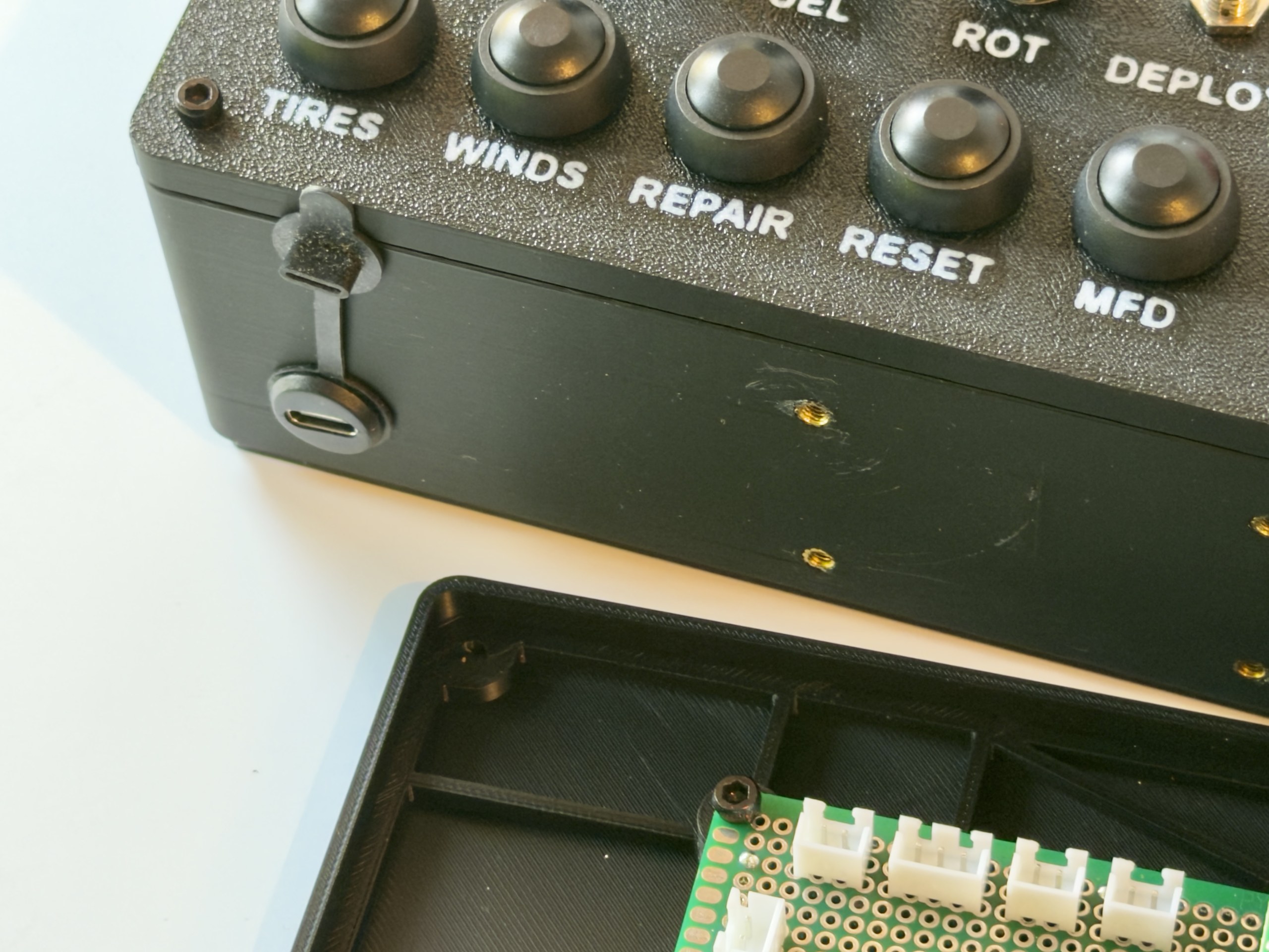
- Dry-fit the USB-C socket in the side wall (hole Ø 13.2 mm with a 10.1 mm flat).

5.3 The bracket
The bracket is rigid, without joints: the angle is built into the part. It turns the box towards the driver by about 35°. The arm has a solid core of about 40 × 30 mm with two 5 mm vertical fins, as tall as the plate on the profile (93 mm). staffa_l (box on the left of the wheel) and staffa_r (box on the right) are mirror images of each other, with the same sizes. Printed in PETG with 5 walls, the bracket is rock solid.
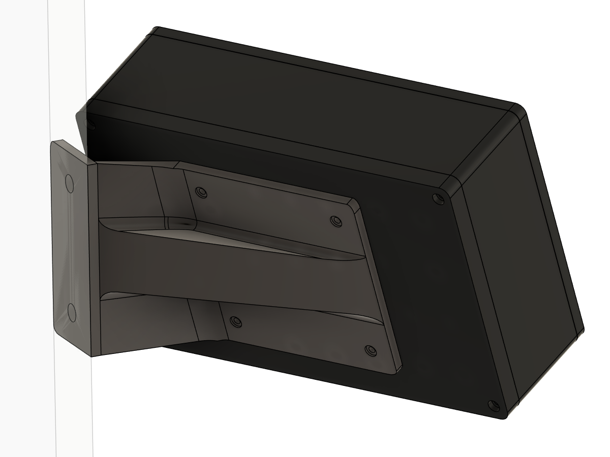
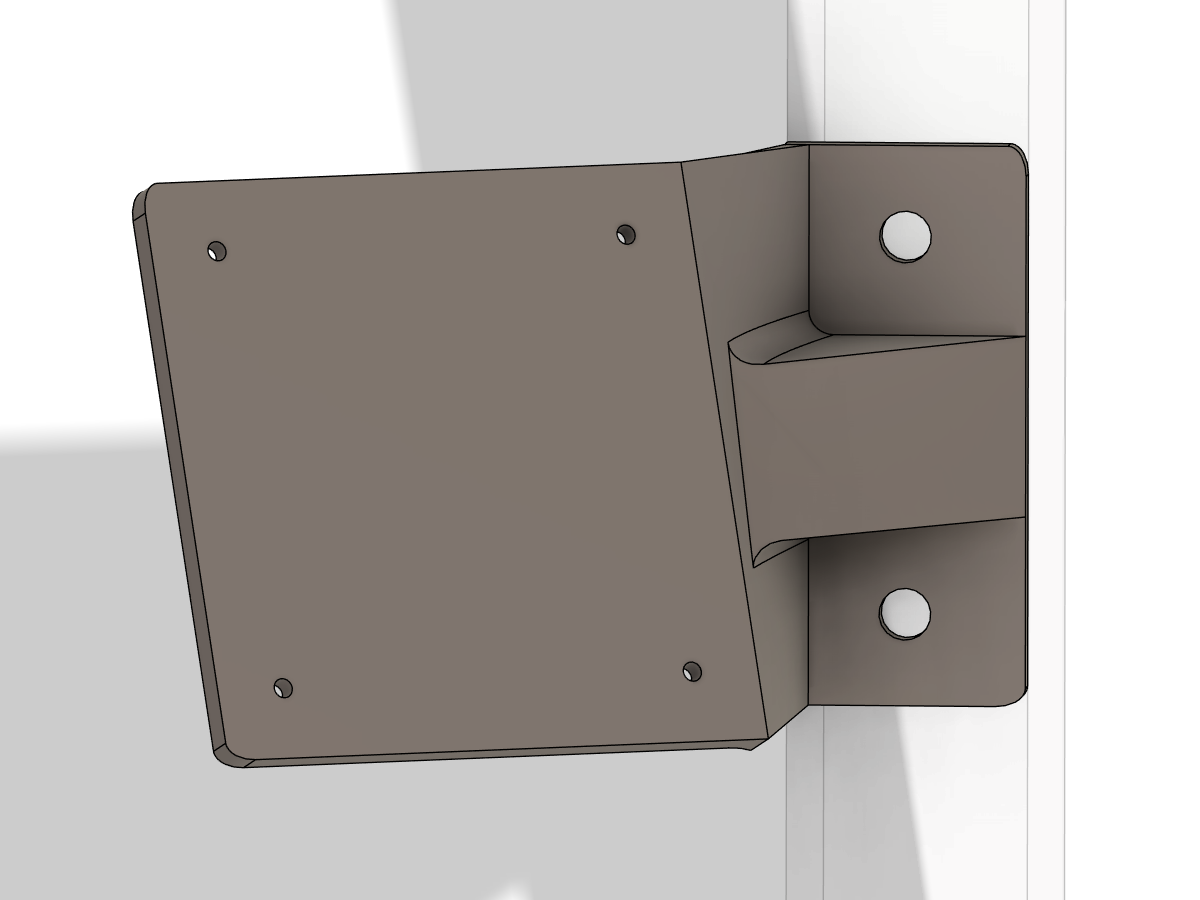
| Bracket data | Value |
|---|---|
| Plate on the profile | 93 × 40 × 5 mm, two Ø 8.6 mm holes in line, 62.6 mm apart, along the profile |
| Profile | 40 × 80 aluminium, two M8 T-nuts in one slot. On the 40 mm face the plate covers the full width; on the 80 mm face the holes line up with one of the two slots. |
| Box side | VESA 75 × 75, four Ø 3.3 mm holes, centred on the box |
| Position | Box centre about 105 mm from the profile face; far corner about 205 mm |
6. Build the main board
This is the longest step. You will solder the Teensy sockets, 29 connectors and a few small parts on the perfboard, then join them with thin wires on the underside. Take it one wire at a time and check each one: built and checked this way, the board works at the first power-up.
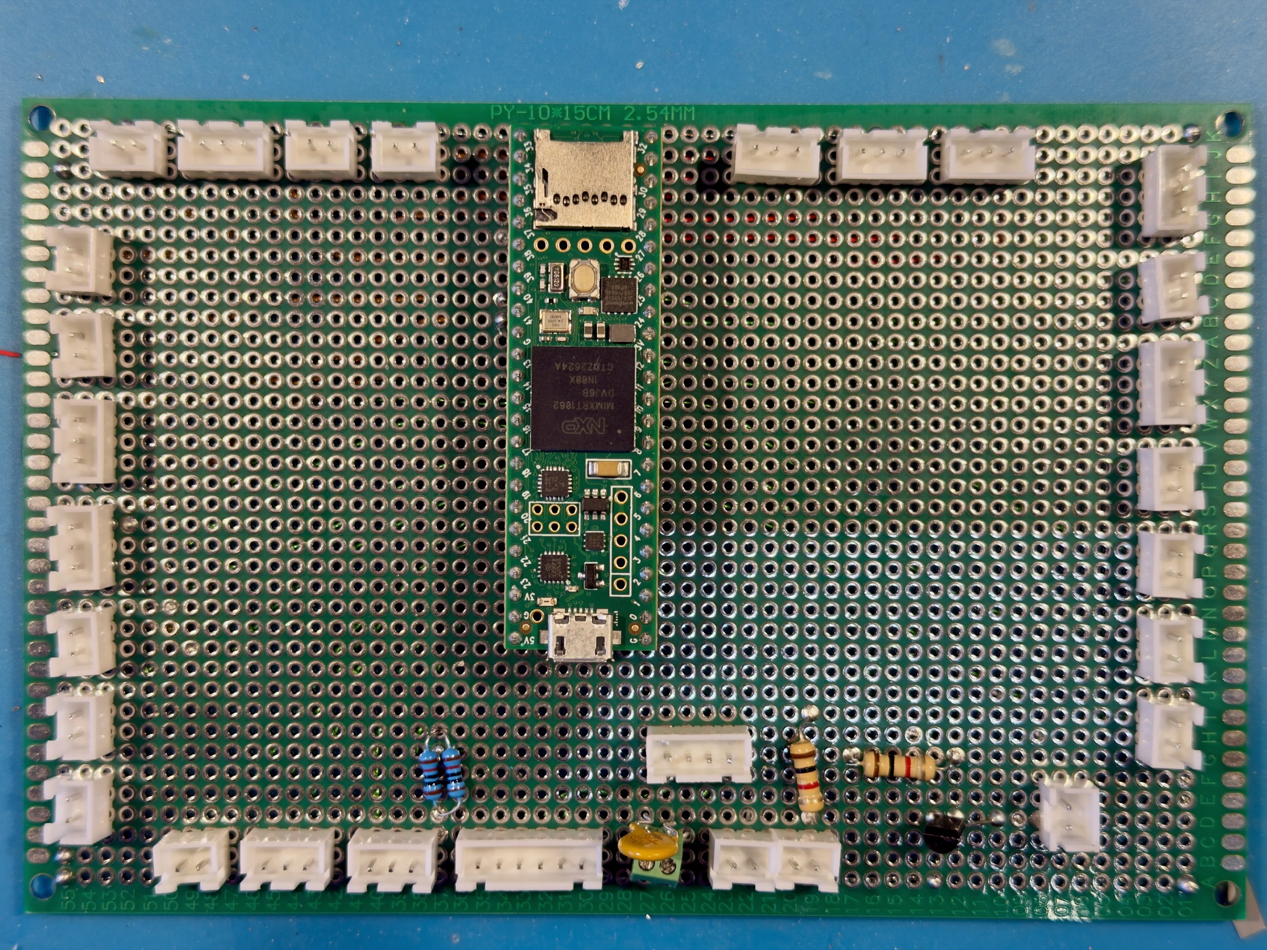

6.1 Finding your way on the board
The perfboard has 55 columns and 37 rows of holes. Two coordinate systems are used in this guide:
| System | Columns | Rows | Example (PTTalk signal) |
|---|---|---|---|
| Printed (on the board) | 01–55, 01 on the right when you look at the component side | A…Z then A′…K′, counted from the bottom | 38-J′ |
| Diagram “c;r” | 1 = left of the component side | 1 = top | 18;2 |
Conversion: printed column = 56 − diagram column; printed row counted from the bottom = 38 − diagram row. When you work on the board, always use the printed coordinates (they are printed next to the holes). In this guide the printed coordinate is written first and the diagram coordinate, when given, in brackets.
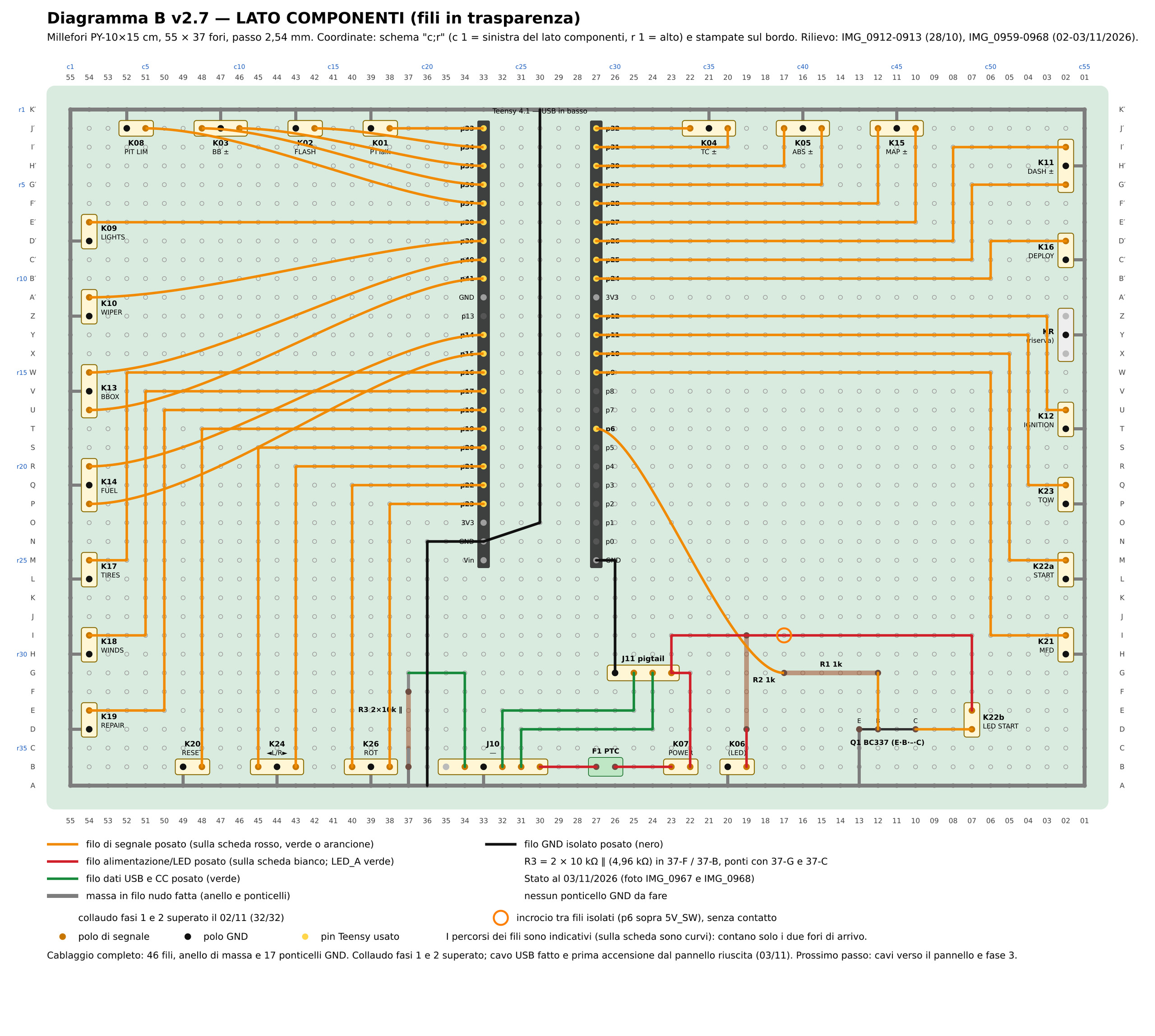
6.2 Build order
- Teensy sockets. Push the two 1 × 24 socket strips onto the Teensy pins, then insert the whole thing in the board: left strip in printed column 33, right strip in column 27, from row J′ (top) down to row M (24 holes), USB port towards the bottom edge. Solder one pin at each end of each strip, check that the strips are flat and straight, then solder the remaining pins. The Teensy acts as a jig and keeps the strips perfectly aligned. Remove the Teensy afterwards and keep it away from the soldering area.
Pins that the box does not use (right strip p0–p5 and p7; left strip 3V3) may be left unsoldered. Never connect anything to the Teensy 3V3 or Vin pins.
- Connector headers. Solder the 29 JST-XH headers at the positions of Table 6.1. Solder one corner pin first, check that the header sits flat and square, then the others. Do not overheat the plastic. The header pitch is 2.50 mm and the board 2.54 mm: the pins go in with a little pressure, which is normal.
- Fuse holder and small parts (Table 6.2): screw terminal for the PTC, resistors R1 and R2, the two 10 kΩ resistors of R3, transistor Q1. Measure every resistor with the multimeter before soldering it: 5.1 Ω and 5.1 kΩ, for example, differ only by one colour band.
- Ground ring. Run a bare tinned wire all around the board: row K′ (top), column 01, row A (bottom), column 55, closing the ring. Solder it every 4–5 holes. Then join every GND pole of the connectors to the ring with a short bare jumper (Table 6.3). In the diagrams, the GND pole is the black dot.
- Signal wires. Lay the 33 signal wires (28 AWG PTFE) from the socket pin to the connector pole, following Table B.1 in Appendix B. Strip 2–3 mm, tin the end, solder. After each wire, check continuity between its two ends and that it does not beep to the ground ring.
- Power, USB and ground wires (Table 6.4). Use insulated wire for all of them.
- Clean the board with isopropyl alcohol and a toothbrush, let it dry, and inspect every joint with a magnifier, looking for solder bridges between adjacent holes.
6.3 Connector positions
Pole 1 is the first one at the top on the left and right edges, and the first one on the left (component side) on the top and bottom rows. On all 3-pin connectors pole 2 (the middle one) is GND. Connector names (K01…K26, J10, J11) are also used by the firmware diagnostics.
| Conn. | Pins | Edge | Control | Pole 1 | Pole 2 | Pole 3 |
|---|---|---|---|---|---|---|
| K08 | 2 | top left | PIT LIM | GND 52-J′ (4;2) | p37 51-J′ (5;2) | |
| K03 | 3 | top left | BB ± | p36 48-J′ (8;2) | GND 47-J′ (9;2) | p35 46-J′ (10;2) |
| K02 | 2 | top left | FLASH | GND 43-J′ (13;2) | p34 42-J′ (14;2) | |
| K01 | 2 | top left | PTTalk | GND 39-J′ (17;2) | p33 38-J′ (18;2) | |
| K04 | 3 | top right | TC ± | p32 22-J′ (34;2) | GND 21-J′ (35;2) | p31 20-J′ (36;2) |
| K05 | 3 | top right | ABS ± | p30 17-J′ (39;2) | GND 16-J′ (40;2) | p29 15-J′ (41;2) |
| K15 | 3 | top right | MAP ± | p28 12-J′ (44;2) | GND 11-J′ (45;2) | p27 10-J′ (46;2) |
| K09 | 2 | left | LIGHTS | p38 54-E′ (2;7) | GND 54-D′ (2;8) | |
| K10 | 2 | left | WIPER | p39 54-A′ (2;11) | GND 54-Z (2;12) | |
| K13 | 3 | left | BBOX | A p40 54-W (2;15) | GND 54-V (2;16) | B p41 54-U (2;17) |
| K14 | 3 | left | FUEL | A p14 54-R (2;20) | GND 54-Q (2;21) | B p15 54-P (2;22) |
| K17 | 2 | left | TIRES | p16 54-M (2;25) | GND 54-L (2;26) | |
| K18 | 2 | left | WINDS | p17 54-I (2;29) | GND 54-H (2;30) | |
| K19 | 2 | left | REPAIR | p18 54-E (2;33) | GND 54-D (2;34) | |
| K20 | 2 | bottom left | RESET | GND 49-B (7;36) | p19 48-B (8;36) | |
| K24 | 3 | bottom left | ◄L/R► | p20 45-B (11;36) | GND 44-B (12;36) | p21 43-B (13;36) |
| K26 | 3 | bottom left | ROT | A p22 40-B (16;36) | GND 39-B (17;36) | B p23 38-B (18;36) |
| K11 | 3 | right | DASH ± | p26 02-I′ (54;3) | GND 02-H′ (54;4) | p25 02-G′ (54;5) |
| K16 | 2 | right | DEPLOY | p24 02-D′ (54;8) | GND 02-C′ (54;9) | |
| KR | 3 | right | spare, not wired | 02-Z (54;12) | GND 02-Y (54;13) | 02-X (54;14) |
| K12 | 2 | right | IGNITION | p12 02-U (54;17) | GND 02-T (54;18) | |
| K23 | 2 | right | TOW | p11 02-Q (54;21) | GND 02-P (54;22) | |
| K22a | 2 | right | START contact | p10 02-M (54;25) | GND 02-L (54;26) | |
| K21 | 2 | right | MFD | p9 02-I (54;29) | GND 02-H (54;30) | |
| K07 | 2 | bottom | POWER switch | 5V_IN 23-B (33;36) | 5V_SW 22-B (34;36) | |
| K06 | 2 | bottom | power LED | GND (cathode) 20-B (36;36) | anode 19-B (37;36) | |
| K22b | 2 | bottom right | START lamp | LED + (5V_SW) 07-E (49;33) | LED − (Q1 collector) 07-D (49;34) | |
| J11 | 4 | bottom | micro-USB pigtail | 1 GND 26-G (30;31) · 2 D− 25-G (31;31) · 3 D+ 24-G (32;31) · 4 5V_SW 23-G (33;31) | ||
| J10 | 6 | bottom | USB-C socket | 1 empty 35-B (21;36) · 2 CC 34-B (22;36) · 3 GND 33-B (23;36) · 4 D− 32-B (24;36) · 5 D+ 31-B (25;36) · 6 VBUS 30-B (26;36) | ||
6.4 Small parts
| Part | Holes (printed) | Connection / notes |
|---|---|---|
| F1 PTC 0.5 A in screw terminal | 27-B and 26-B | Between VBUS and 5V_IN |
| R1 1 kΩ, horizontal | 17-G and 12-G | From p6 to the base of Q1. Bend its lead on to 12-D (base of Q1). |
| R2 1 kΩ, vertical | 19-I and 19-D | From 5V_SW to the anode of the power LED (K06-2) |
| R3 = 2 × 10 kΩ in parallel, vertical | 37-F and 37-B (both resistors share the same two holes) | Solder-bridge 37-F to 37-G (where the CC wire arrives) and 37-B to 37-C (bare jumper down to the ring at 37-A) |
| Q1 BC337 | E 13-D · B 12-D (middle leg) · C 10-D (bend the leg) | Emitter to the ring with a bare jumper 13-D → 13-A. Collector to K22b-2 with an insulated wire 10-D → 07-D (careful: 07-E, just above, is 5V_SW). |
6.5 Ground connections
| Where | What to join |
|---|---|
| Ring | Bare wire along row K′, column 01, row A, column 55, closed |
| Left edge | GND poles 54-D′, 54-Z, 54-V, 54-Q, 54-L, 54-H, 54-D → column 55 (next hole) |
| Top edge | GND poles 52-J′, 47-J′, 43-J′, 39-J′ and 21-J′, 16-J′, 11-J′ → row K′ (hole above) |
| Right edge | GND poles 02-H′, 02-C′, 02-Y, 02-T, 02-P, 02-L, 02-H → column 01 (next hole) |
| Bottom edge | 49-B, 44-B, 39-B, 33-B (J10 GND), 20-B (K06) → row A (hole below); R3: 37-C → 37-A; Q1 emitter: 13-D → 13-A |
| Teensy GND | Insulated black wire from the left socket GND pin 33-N to the ring at the bottom (36-A), plus a second one to the ring at the top |
| J11 GND | Insulated black wire 26-G → right socket GND pin 27-M |
6.6 Power and USB wiring
| Net | From | To | Notes |
|---|---|---|---|
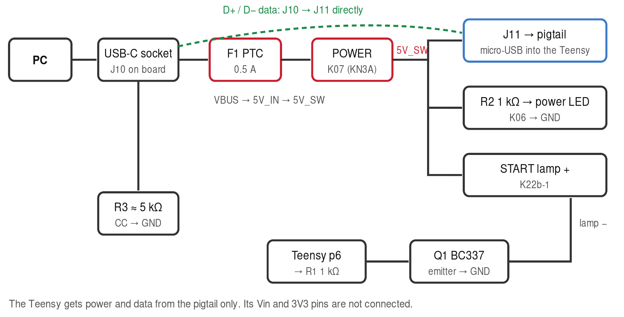
| VBUS | J10-6 30-B | F1 27-B | USB 5 V, before the fuse |
| 5V_IN | F1 26-B | K07-1 23-B | After the fuse, to the POWER switch |
| 5V_SW | K07-2 22-B | J11-4 23-G | Switched 5 V to the Teensy pigtail |
| 5V_SW | J11-4 23-G | R2 top 19-I | To the power LED resistor |
| 5V_SW | R2 top 19-I | K22b-1 07-E | To the START lamp (+). Crosses the p6 wire: both must be insulated. |
| LED_A | R2 bottom 19-D | K06-2 19-B | Power LED anode |
| D− | J10-4 32-B | J11-2 25-G | USB data, direct |
| D+ | J10-5 31-B | J11-3 24-G | USB data, direct |
| CC | J10-2 34-B | 37-G (bridged to R3) | Without R3, a USB-C to USB-C cable gives no power |
| p6 | right socket 27-T | R1 17-G | Signal to the START lamp transistor |
| Q1 C | 10-D | K22b-2 07-D | START lamp (−) |
6.7 The power path in one picture


6.8 Check before moving on
- All 33 signal wires present, each tested for continuity end-to-end.
- No signal wire beeps to the ground ring.
- Every GND pole beeps to the ring.
- No solder bridges between the socket pins (look at p40–p41, p14–p15, p15–p16 in particular).
- Board cleaned of flux.
7. Make the cables for the controls
Each control gets its own cable, with the control at one end and a JST-XH plug at the other. This takes time, but it pays back: a faulty switch is replaced by unplugging one connector, without touching anything else.
7.1 Rules for all cables
| # | Rule | Why |
|---|---|---|
| 1 | One cable per connector, 26 AWG silicone wire. XH plug crimped at the board end. | Each control can be replaced alone. |
| 2 | First solder or crimp the control end with long wires. Cut to length (route + 5–8 cm) and crimp the XH plug only when the board is in its place in the bottom. | Enough slack to open the box. |
| 3 | Black is always GND. On 3-wire cables use the same two colours for poles 1 and 3 every time, with GND (black) always on pole 2. | Readable at a glance, no crossed wires. |
| 4 | Twist the wires of each cable lightly (2–3 turns every 10 cm). | Tidy, less noise. |
| 5 | Label both ends with the connector name (K01…). Label K22a and K22b clearly: they use the same plug. | 2-pin and 3-pin plugs are easy to swap by mistake. |
| 6 | Slide heat-shrink (about 10 mm, Ø 2–3 mm) on the wire before soldering. | You cannot add it afterwards. |
| 7 | Test every finished cable with the multimeter: continuity end to end; no continuity between different poles; open at rest, closed when the control is operated. | Faults found before assembly. |
| 8 | Plug and unplug cables only with the USB cable disconnected or POWER off. | K07, K06 and K22b carry 5 V. |
7.2 How each type of control is connected
| Control | Wires | Control end | Connection to the plug |
|---|---|---|---|
| PBS-33B button | 2 | Soldered, heat-shrink | The two tabs are equivalent: either one to either pole. |
| MTS-123 toggle ± | 3 | 2.8 mm faston | Middle pin → pole 2 (GND); outer pins → poles 1 and 3 in any order (the direction is fixed in the firmware if needed). |
| MTS-101 toggle on/off | 2 | 2.8 mm faston | Either pin to either pole. |
| EC11 encoder | 3 | Soldered on the 3-pin side (A – C – B), heat-shrink | C (middle) → pole 2 (GND), A → pole 1, B → pole 3. The two pins on the other side (push switch) stay free: do not cut them. Add strain relief with hot glue or a tie. |
| KN3A-101 covered toggle | 2 | Screw terminal with a crimped 0.25 mm² ferrule (never a tinned wire end) | IGNITION (K12), TOW (K23): either terminal to either pole. POWER (K07): terminal 1 → pole 1 (5V_IN), terminal 2 → pole 2 (5V_SW). |
| START button 22 mm | 4 | XH contacts crimped on its own wires | The two green wires (contact) → K22a (either pole). Red (lamp +) → K22b pole 1; black (lamp −) → K22b pole 2. If your button has different colours or more wires, identify contact and lamp with the multimeter first. |
| LED 5 mm | 2 | Soldered, heat-shrink on each leg | Cathode (short leg, flat side) → K06 pole 1; anode → K06 pole 2. Reversed, it simply does not light. |
7.3 Crimping JST-XH contacts
- Strip about 2 mm of insulation. 26 AWG is thin: if the contact does not hold it well, strip 4 mm and fold the copper back on itself.
- Place the contact in the SN-01BM pliers in the smallest die, wire inserted so that the copper sits under the front wings and the insulation under the rear wings.
- Squeeze fully. The front wings must wrap the copper, the rear wings the insulation.
- Pull the wire firmly: it must not come out.
- Push the contact into the housing, lance upwards, until it clicks. Pull lightly to confirm it is locked.
7.4 Faston terminals on thin wire
Common faston terminals are meant for 0.5–1.5 mm² wire, much thicker than 26 AWG (about 0.13 mm²). They work well with these tricks:
| Trick | How |
|---|---|
| Fold the copper | Strip 8–10 mm and fold the copper back twice (3–4 layers) |
| Fatten the insulation | Shrink 1–2 cm of heat-shrink tubing on the wire, then crimp the rear wings over it |
| Pliers | SN-02C, smallest cavity; slide the insulating sleeve on before crimping |
| Checks | The faston slides on tightly and does not rotate; a firm pull does not remove the wire; three fastons side by side on the MTS-123 do not touch. If a check fails: squeeze the wings again or solder. |
7.5 Cable list
| Cable | Control | Part | Plug | Cable | Control | Part | Plug |
|---|---|---|---|---|---|---|---|
| K01 | PTTalk | PBS-33B | 2-pin | K14 | FUEL | EC11 | 3-pin |
| K02 | FLASH | PBS-33B | 2-pin | K15 | MAP ± | MTS-123 | 3-pin |
| K03 | BB ± | MTS-123 | 3-pin | K16 | DEPLOY | MTS-101 | 2-pin |
| K04 | TC ± | MTS-123 | 3-pin | K17 | TIRES | PBS-33B | 2-pin |
| K05 | ABS ± | MTS-123 | 3-pin | K18 | WINDS | PBS-33B | 2-pin |
| K06 | power LED | LED 5 mm | 2-pin | K19 | REPAIR | PBS-33B | 2-pin |
| K07 | POWER | KN3A-101 | 2-pin | K20 | RESET | PBS-33B | 2-pin |
| K08 | PIT LIM | PBS-33B | 2-pin | K21 | MFD | PBS-33B | 2-pin |
| K09 | LIGHTS | MTS-101 | 2-pin | K22a | START contact | 22 mm button | 2-pin |
| K10 | WIPER | MTS-101 | 2-pin | K22b | START lamp | 22 mm button | 2-pin |
| K11 | DASH ± | MTS-123 | 3-pin | K23 | TOW | KN3A-101 | 2-pin |
| K12 | IGNITION | KN3A-101 | 2-pin | K24 | ◄L/R► | MTS-123 | 3-pin |
| K13 | BBOX | EC11 | 3-pin | K26 | ROT | EC11 | 3-pin |
Totals: on the board side 61 XH contacts for the controls plus 9 for J10 and J11. On the controls side: 18 fastons on the MTS-123, 6 on the MTS-101, 6 ferrules on the KN3A, 4 XH contacts on the START button, solder joints on PBS-33B (16), EC11 (9) and LED (2).
7.6 The two USB cables inside the box
| Cable | How to make it |
|---|---|
| USB-C socket → J10 | Crimp XH contacts on the 5 wires of the socket and insert them in a 6-pin housing: pole 1 empty, 2 green (CC), 3 black (GND), 4 white (D−), 5 blue (D+), 6 red (VBUS). |
| Micro-USB pigtail → J11 | Cut the USB-A plug off the data cable, leaving 15–20 cm on the micro-USB side. Crimp XH contacts on the 4 wires into a 4-pin housing: 1 black (GND), 2 white (D−), 3 green (D+), 4 red (VBUS). |
8. Test 1 — multimeter check of the bare board
This test is done with the multimeter only, Teensy not plugged in and nothing connected. It catches short circuits that could destroy the Teensy. Use the continuity (beep) range unless stated otherwise. Coordinates are the printed ones.
| Check | Expected result |
|---|---|
| Every signal pole ↔ 5V_SW (K07 pole 2, hole 22-B) | No continuity |
| 5V_SW (22-B), 5V_IN (23-B), VBUS (30-B), J11-4 (23-G), K06-2 (19-B) ↔ ground ring | No continuity |
| Every socket hole used by a control ↔ the pole of its connector (Table B.1) | Continuity |
| Every GND pole ↔ ground ring | Continuity |
| Every signal pole ↔ ground ring | No continuity |
| 5V_SW chain: K07-2 ↔ J11-4 ↔ R2 top (19-I) ↔ K22b-1 (07-E) | Continuity |
| VBUS (30-B) ↔ K07-1 (23-B) with the PTC in its terminal | Continuity |
| J10 D− ↔ J11-2; J10 D+ ↔ J11-3; D+ ↔ D− | Continuity; none between D+ and D− |
| CC (34-B) ↔ ground ring, resistance range | About 5 kΩ (4.96 kΩ) |
| Neighbouring socket pins: p40 ↔ p41, p14 ↔ p15, p15 ↔ p16 | No continuity |
| p6 wire ↔ 5V_SW where they cross | No continuity |
| Q1 in diode-test range (base–emitter, base–collector) | Conducts in one direction only |
9. Install the firmware
The firmware is the program that turns the Teensy into a keyboard and joystick. You load it once, from a Windows PC, with the free Arduino IDE. No programming is needed. The file buttonbox_firmware.ino is in the firmware download at the top of this article; its header contains the same instructions in short form.
For this step plug the Teensy into a USB port of the PC directly with a micro-USB data cable (not through the box).
9.1 Install the software (once)
- Download and install Arduino IDE 2.x from arduino.cc/en/software. Use the normal Windows installer or ZIP: the Microsoft Store version does not work with Teensy.
- Start the IDE. Open File › Preferences. In Additional boards manager URLs paste:
https://www.pjrc.com/teensy/package_teensy_index.json
and click OK. - Click the Boards Manager icon on the left, type teensy, click Install on the Teensy package and wait until it finishes (this guide was tested with version 1.62.0).
9.2 Open the firmware and choose the settings
- Put
buttonbox_firmware.inoin a folder named buttonbox_firmware (same name as the file). Open it with File › Open. If the folder is missing, the IDE offers to create it. - In the Tools menu set:
Menu Value Tools › Board Teensy 4.1 Tools › USB Type Serial + Keyboard + Mouse + Joystick All other settings Leave the defaults
9.3 Upload
Normal way. Click the Upload button (right arrow). The program is compiled, the small Teensy Loader window opens and programs the board. If asked, press the small white button on the Teensy. At the end the Teensy restarts with the new program.
If Upload does not work (often a firewall or antivirus blocks the Teensy tools, with a message such as “Unable to find Teensy Loader… firewall blocking localhost?”):
- Choose Sketch › Export Compiled Binary. A file ending in
.hexappears in thebuildsubfolder of the sketch folder. - Download the stand-alone Teensy Loader from pjrc.com/teensy/loader.html and start it.
- File › Open HEX File and select the
.hexfile. - Press the white button on the Teensy, then click Program and then Reboot. You should read “Download Complete” and “Reboot OK”.
Alternatively, allow teensy.exe and teensy_post_compile.exe (in the Teensy tools folder of the Arduino IDE) through the Windows firewall on private networks; then Upload works normally.
9.4 Updating the firmware later
Once the box is closed and mounted on the rig you do not need to open it: data and power go through the box’s own USB-C cable. Close iRacing, open the sketch and click Upload. With the firewall exceptions above, the Arduino IDE restarts the Teensy by itself, without the white button.
After an update that changes a key, delete the old assignment in iRacing and assign the function again from the box (Chapter 14).
10. Test 2 — bare board with a jumper wire
Now the Teensy goes into the board, with the firmware loaded but no control connected. With a jumper wire you “press” each control by hand and the firmware tells you, on screen, which one it sees.
10.1 Plug in the Teensy
Chip side up, USB port towards the bottom edge. Press it all the way down, evenly, until the black plastic spacer of its pins rests on the sockets along the whole length. A half-inserted Teensy gives dead or intermittent inputs. Power it with the micro-USB cable directly from the PC (the pigtail is not used yet).
10.2 Open the diagnostics
- In the Arduino IDE choose the Teensy port in Tools › Port, then open Tools › Serial Monitor.
- At the bottom of the Serial Monitor set the line ending to Newline (any setting works).
- A banner appears. Type
nand press Enter: “no keys” mode. The box keeps reading and printing, but sends nothing to the PC, so your jumper tests will not type shortcuts into other programs. - Type
t+ Enter: self-test at rest (do not touch anything).
Expected output of t |
Meaning |
|---|---|
Riposo: tutti i 40 pin a 1 - OK |
At rest all 40 pins (32 used + 8 free) read “open”: no pin stuck to ground |
Corti tra segnali: nessuno - OK |
No short circuit between two signal pins |
10.3 Test every connector
- 2-pin connectors: touch the signal pole and the GND pole of the header with the jumper. One line appears, for example:
TIRES     K17-1  p16 CHIUSO
TIRES     K17-1  p16 aperto
Check that the name and the connector match the one you are testing.
- 3-pin toggle connectors: jumper pole 1 to pole 2, then pole 3 to pole 2. Two different lines (e.g.
BB +andBB -). - Encoder connectors (K13, K14, K26): a single jumper touch is not a full “click”, so no line is printed; they are checked by the checklist in the next step, or with
p40,p41… (pin monitor,qto stop). - Type
s+ Enter. The checklist must readprovati 32/32(32 of 32 contacts tested) followed byCOMPLETO(complete). If some are missing, they are listed aftermanca:.
The START lamp output is tested later, with the button connected. To leave “no keys” mode type n again, or simply close the Serial Monitor: closing it always restores normal operation.
11. Assemble the box
Mount the controls in the panel, put the board in the bottom, connect everything. Leave the box open until Test 3 (Chapter 12) is passed.
11.1 Mount the controls
The labels plate (top) lies on the front of the case, and the nut of each control clamps both together (3 mm in total). Mount from the inside, nut on the outside.
| Control | How |
|---|---|
| MTS-123 / MTS-101 | The tab of the washer goes into the small anti-rotation notch. Choose the notch so that the lever moves vertically (◄L/R► horizontally). |
| EC11 encoders | Cut off the small anti-rotation tooth, or lodge it in a notch. Turn all three encoders the same way, pins towards the cable route. The mark on the knob has no meaning. |
| KN3A covered toggles | Check that the open covers do not touch each other. |
| All | The top plate eats about 1 mm of thread: make sure each nut grips at least two full turns. Tighten firmly but without forcing the plastic. |

11.2 Board, USB and cables
- Fit the USB-C socket in the side wall and tighten its nut.
- Secure the board on the bottom so that it cannot slide: M3 standoffs fixed to the bottom, or thick double-sided foam tape. Nothing metallic may touch the wires under the board.
- Plug the micro-USB pigtail into the Teensy and its XH plug into J11; plug the USB-C socket cable into J10. Secure the pigtail near the micro plug with a small cable tie or a drop of hot glue, so it cannot pull on the Teensy port.
- With the bottom placed next to the case, cut each control cable to length (route + 5–8 cm), crimp its XH plug (Chapter 7.3) and plug it into its connector, checking the label. USB disconnected while you do this.
- Route the cables tidily and bundle them loosely. Replace any paper tape with Kapton tape.
12. Test 3 — the complete box
Everything connected, box still open. Now you power the box from its own USB-C socket and check every control, the lamps and the keys.
12.1 Power
| Check | Expected result |
|---|---|
| All levers down, POWER up, box connected to the PC through its USB-C socket | Power LED on; Windows plays the “device connected” sound |
| POWER down / up | The device disappears / reappears; the LED follows |
| USB-A → USB-C cable and USB-C ↔ USB-C cable, plug both ways round | Recognised in every case |
| DC voltage between 22-B (5V_SW) and the ground ring | About 5 V |
12.2 Every control, with the diagnostics
- Open the Serial Monitor (Chapter 10.2) and type
n(no keys). - Type
t. Expected: the two “OK” lines. A lever left up appears asA RIPOSO CHIUSO(closed at rest): lower it and repeat. - Operate every control slowly, one at a time, and read the line that appears. Toggles: lever up must give the “+” name (e.g.
BB +); for ◄L/R►, lever left givesL. Encoders: one click clockwise must printBBOX: +(FUEL, ROT the same). If a direction is reversed, it is fixed in the firmware (Chapter 15) — no rewiring. - Type
s:provati 32/32andCOMPLETO. - Type
b, operate every button and toggle at least 5 times (not the encoders), thenq. The result suggests a debounce time. With the parts of this guide the maximum bounce is around 6 ms and the firmware value (12 ms) is fine. - Type
k30and, without operating anything, shake the cables for 30 seconds. Expected:0 fronti spuri(0 false changes). Anything else means a loose contact or crimp: find it withp<pin>while you wiggle the wires. - Type
l1andl0: the START lamp lights and goes off. Typelato return it to automatic. - Close the Serial Monitor. The box is back in normal mode and sends keys.
12.3 The keys
Now check that the PC receives the right shortcut and that the special behaviours work.
| # | Action | Expected (always with Ctrl+Shift) |
|---|---|---|
| 1 | Hold PTTalk, then FLASH, for 1 s | P / F, released after about 1 s |
| 2 | PIT LIM, TIRES, WINDS, REPAIR, RESET, MFD | Q, F1 … F5, short pulses |
| 3 | Each ± toggle up, then down | BB B/N, TC T/Y, ABS A/S, MAP M/K, DASH D/E; L/R left L, right F11 |
| 4 | Each knob, 1 click clockwise and 1 counter-clockwise | BBOX O/I, FUEL U/J, ROT G/H |
| 5 | Each knob, 10 fast clicks | 10 keys, none lost (very fast spins are queued and may arrive with a short delay) |
| 6 | LIGHTS and WIPER up and down | F6 / F7 at every change |
| 7 | DEPLOY up, then down | No key. In Windows Game Controllers (Win+R, joy.cpl, Properties) button 1 lights up and goes off. |
| 8 | START with IGNITION down | No key |
| 9 | IGNITION up | F8 at once, and the START lamp lights |
| 10 | IGNITION down and leave it | Lamp off at once; F8 after about 2 s |
| 11 | IGNITION up, then down and up again within 2 s | One F8 only, on the way up; lamp off only during the flick |
| 12 | Hold START with IGNITION up | F10, held until you release |
| 13 | Hold START, then lower IGNITION | F10 released at once, lamp off; F8 after about 2 s |
| 14 | TOW up and leave it | F9, released after 5 s |
| 15 | TOW down and leave it | F9, released after 5 s |
| 16 | TOW up, then down after 2 s | F9, released after about 2 s (cancelled); no new F9 |
When everything is correct, fit the bottom into the case and screw it.
13. Mount the box on the rig
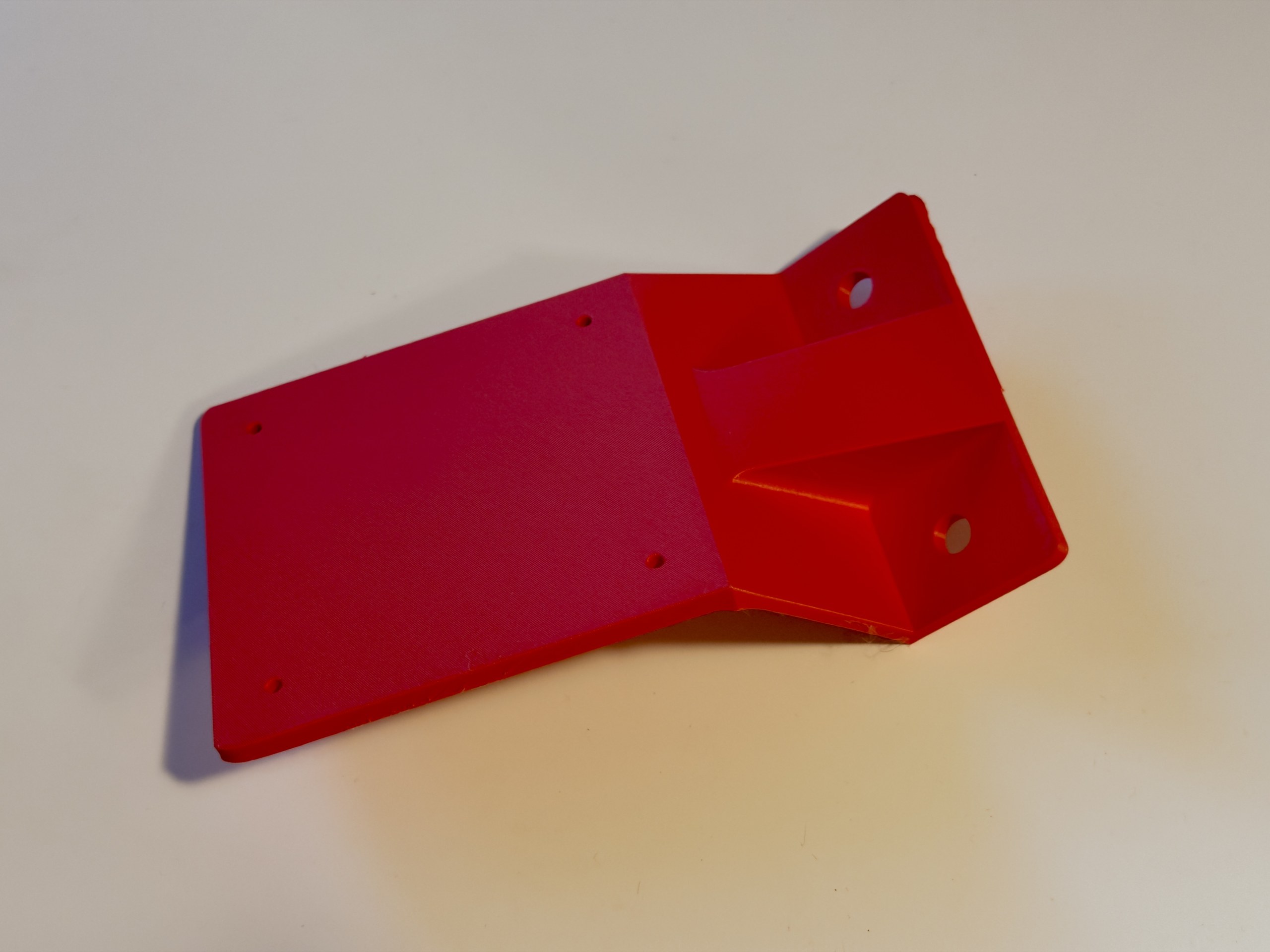

- Check that you printed the right bracket:
staffa_lif the box sits on the left of the wheel (as in the photos),staffa_rif it sits on the right. - Slide two M8 T-nuts into one slot of the 40 × 80 profile.
- Fix the bracket with two M8 bolts and a DIN 9021 washer under each head. Tighten firmly but do not crush the plastic. The plate must lie flat on the profile.
- Fix the box to the bracket with four M3 screws into the inserts of the bottom (VESA 75 × 75).
- Route the USB cable so that it cannot be caught by the wheel or your legs.
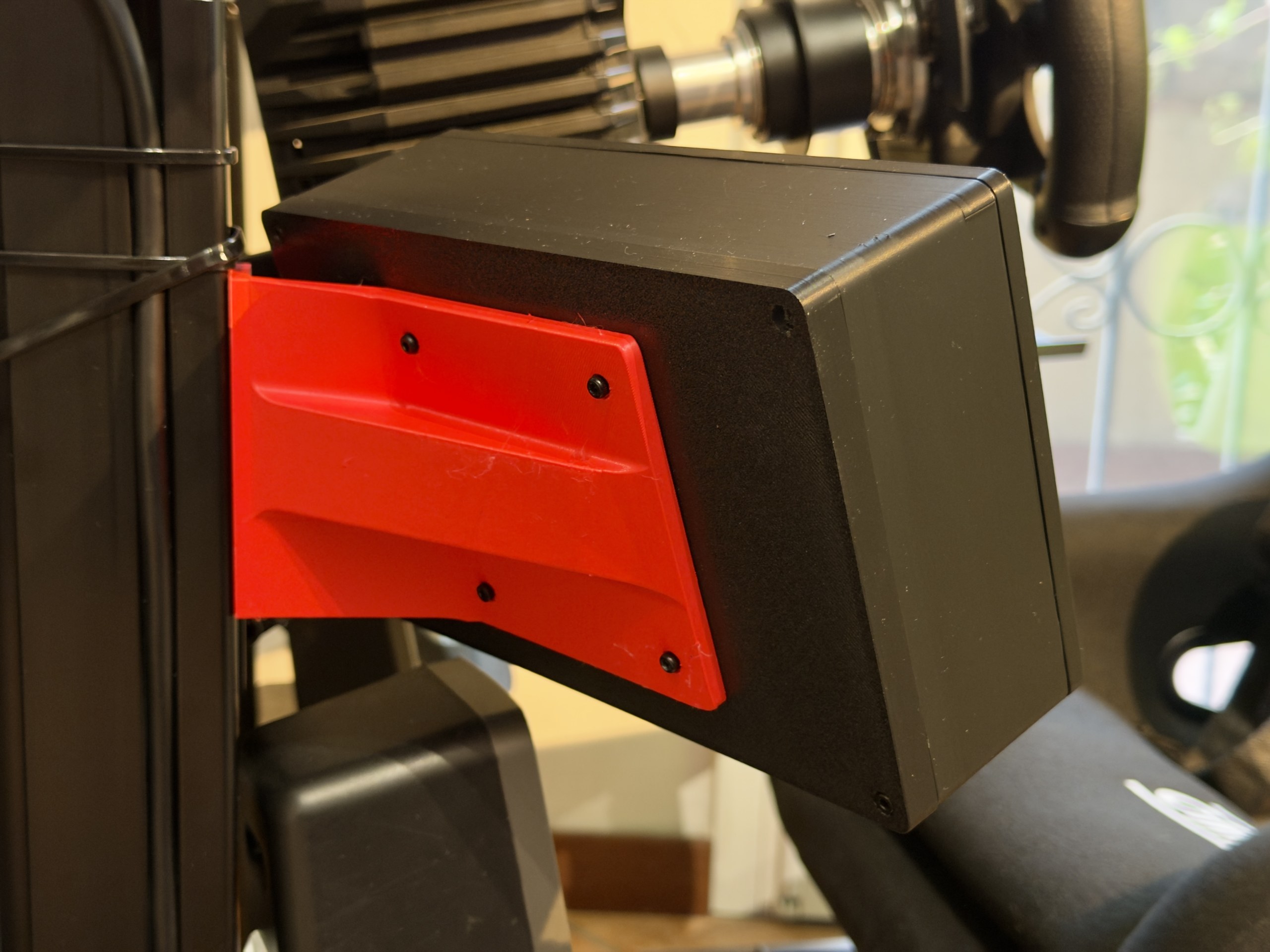
Checks
| # | Check | How | Expected |
|---|---|---|---|
| 1 | Fit | Bolts through the holes, plate on the profile | Bolts enter without reaming; plate flat |
| 2 | Clearance | Box corner near the profile; reach of all controls | No contact; everything reachable |
| 3 | Vibration | A session with your usual force feedback | No vibration or buzzing of the box |
| 4 | Stiffness | Flick the far toggles hard (◄L/R►, BB, TC), press TIRES and WINDS | No noticeable movement |
| 5 | Creep | Mark the far edge against a fixed reference, check again after 1–2 weeks | No visible sag |
| 6 | Bolts | Check the M8 bolts after a few sessions | Still tight |
14. Set up iRacing

Every function is assigned by operating the box itself in the iRacing Controls screen. The functions that depend on the car (TC, ABS, engine map, dash pages, lights, wipers, deploy) only appear when that car is loaded: available functions are shown in black, the others in grey. So make the assignments in the garage, with each car you drive.
14.1 Procedure
- Switch the box on before starting iRacing, with all levers OFF, and switch it off only after closing the sim. A device that disappears while the sim is running can make it lose its bindings. If the box shares a USB hub with other rig devices, use a powered hub.
- Load a GT3 car in the garage and open Options › Controls. For each line of Table 14.1, click the function and then operate the matching control on the box. The field must show CTRL+SHIFT+ and the key (for example
CTRL+SHIFT+T); if it shows only the key, see Chapter 16.8. DEPLOY is joystick button 1. - Type the texts of Table 14.2 into the chat macro fields of iRacing (Auto Text Chat, 15 macros; the column “Macro” is the number used in this guide, any free number works). Then, in Options › Controls, assign each chat macro to its control on the box, as in step 2.
- If your wheel has buttons for the same functions, assign each function to only one device (wheel or box), so that nothing is triggered twice.
- Repeat step 2 with every other car you drive (other GT3 cars, GTP cars for deploy, engine map and hybrid modes). Check that the assignments already made are still there when you change car.
- First drive: at low speed, use every control once and check that only its own function reacts (no chat window opening, no black box changing, engine still running) and that “+” on the toggles and clockwise on the knobs go the way you expect.
14.2 Mapping
| Box control | Key | iRacing function | Type |
|---|---|---|---|
| PTTalk | P |
Push To Talk | general |
| FLASH | F |
Headlight Flash | general |
| BB ± | B / N |
Brake bias increase / decrease | general |
| TC ± | T / Y |
Traction control + / − | car |
| ABS ± | A / S |
ABS + / − | car |
| MAP ± | M / K |
Throttle shape + / − (the engine map of GT3 cars; on other cars engine map or fuel mixture) | car |
| DASH ± | D / E |
Dash page + / − (or Dash page 2, depending on the car) | car |
| LIGHTS | F6 |
Headlights | car |
| WIPER | F7 |
Wipers | car |
| DEPLOY | joystick button 1 |
DRS / hybrid deploy (held) | car, GTP |
| PIT LIM | Q |
Pit Speed Limiter | general |
| BBOX | O / I |
Next / Previous Black Box | general |
| MFD | F5 |
Select Next Control (of the black box) | general |
| ROT | G / H |
Increment / Decrement Selected Control | general |
| IGNITION | F8 |
Ignition | general |
| START | F10 |
Starter | general |
| TOW | F9 |
Enter / Exit / Tow Car | general |
| FUEL | U / J |
Chat macros, Table 14.2 | macro |
| TIRES · WINDS · REPAIR · RESET | F1 · F2 · F3 · F4 |
Chat macros, Table 14.2 | macro |
| ◄L/R► | L / F11 |
Chat macros, Table 14.2 | macro |
14.3 Chat macros for the pit stop and the chat
The pit buttons, the FUEL knob and the ◄L/R► lever use the official iRacing chat commands. They work with every car and need no change in the firmware: to change what a control does, you change the text of its macro.
| Control | Key | Macro | Macro text | Effect |
|---|---|---|---|---|
| TIRES | F1 |
15 | #!t$ |
Toggles the change of all four tyres: on if it was off, off if it was on |
| WINDS | F2 |
10 | #ws$ |
Ticks the windscreen tear-off |
| REPAIR | F3 |
11 | #fr$ |
Ticks the fast repair |
| RESET | F4 |
14 | #clear$ |
Clears all pit options |
| FUEL + | U |
12 | #fuel +1l$ |
+1 litre at the next stop |
| FUEL − | J |
13 | #fuel -1l$ |
−1 litre at the next stop |
| ◄L | L |
3 | Pass Left$ |
Short text in the chat (any text you like) |
| ◄R | F11 |
4 | Pass Right$ |
Short text in the chat (any text you like) |
| Rule | Details |
|---|---|
Final $ |
Presses Enter: the command runs at once. Without it, the text stays in the chat window waiting for you. |
! after # |
Toggles the option instead of setting it. iRacing keeps the state, so TIRES always matches the black box, even after a change with the mouse or a pit stop. |
| WINDS and REPAIR | They tick their option but do not untick it. To remove them press RESET, then the services you want. |
| Checking | The result is visible in the pit black box (choose it with BBOX). |
| FUEL | Every click is a chat command; the box sends one about every 80 ms. Turn the knob at a steady pace and check the total in the fuel black box. To change the step (for example 5 litres), change the macro text. |
| After the pit exit | By default iRacing asks for the full service again when you leave the pits. With autoResetPitBox=0 in Documents\iRacing\app.ini all options stay unticked instead. |
| Focus | Macros go through the chat: the iRacing window must have the focus. |
| Free macros | 8 of the 15 macros are used; the others are free for your own commands (for example #cleartires$). |
14.4 Driving with the box
| When | What to do |
|---|---|
| Before starting iRacing | All levers OFF, POWER ON |
| In the car | IGNITION up (red lamp in START on), then hold START until the engine runs |
| On track | BB, TC, ABS, MAP with the toggles; DASH for the display pages; BBOX + MFD + ROT for everything else; DEPLOY on the GTP cars |
| Preparing the pit stop | RESET if WINDS or REPAIR must be removed; TIRES to add or remove the tyres; WINDS, REPAIR and FUEL as your strategy needs; check in the pit black box |
| Pit lane | PIT LIM |
| Engine off | IGNITION down and leave it: the engine stops after 2 s |
| After a reset or a return to the garage (lever still up, car off) | Quick flick of IGNITION (down and up within 2 s), then START |
| Car stuck | TOW: one flick of the lever, up or down, and leave it (5 s); a second flick within 5 s cancels |
| End | Close iRacing, then POWER OFF |
15. Adapt the firmware to your box
You do not have to build exactly this layout. All the settings are near the top of buttonbox_firmware.ino, in clearly marked sections. Change a value, save, upload again (Chapter 9.3). If you give the controls other functions, print the top without labels (plate 6) and label it your way, for example with stickers or a label maker.
| I want to… | Change this |
|---|---|
| Use other keys | Section KEYS: e.g. TASTO_PITLIM = KEY_Q → KEY_F13. Names are KEY_A…KEY_Z, KEY_F1…KEY_F24 and so on; they do not depend on the keyboard layout. |
| Send keys without Ctrl+Shift | MODIFICATORI: 0 sends the plain key; combine MODIFIERKEY_CTRL, MODIFIERKEY_SHIFT, MODIFIERKEY_ALT, MODIFIERKEY_GUI with | |
| Fix a toggle working upside-down | Swap its two pins between TOG_PIN_ALTO and TOG_PIN_BASSO (section MEASURED PARAMETERS). Order: BB, TC, ABS, MAP, DASH, L/R. |
| Fix a knob turning the wrong way | Flip its value in ENC_SCAMBIA_AB (order: BBOX, FUEL, ROT) |
| Fix an on/off lever working upside-down | Flip its value in LEVA_ON_IN_ALTO (order: LIGHTS, WIPER, DEPLOY, IGNITION, TOW) |
| Use an encoder with 2 transitions per click | ENC_TRANSIZIONI_PER_SCATTO |
| Cure a button sending a key twice | Raise DEBOUNCE_MS (the b command suggests the value) |
| Change the tow time | T_TOW_MS (milliseconds, default 5000) |
| Change the engine-off delay of IGNITION | T_IGN_OFF_MS (milliseconds, default 2000): how long the lever must stay down before the engine-off pulse, and the time window of the quick flick |
| Change the pause between Ctrl+Shift and the key | T_MODIF_MS (milliseconds, default 20). Raise it to 50 if a game records the key without Ctrl+Shift (Chapter 16.8) |
| Use other pins | Section PINS. Free pins are 0–5, 7 and 8. Never use pin 13 (the Teensy’s own LED). |
| Leave out a control | Just leave its pin unconnected: an open pin sends nothing. |
| Use the overlay with the iRacing labels | #define PROFILO 1 (from v2.6). The default value 0 is the standard layout described in this guide |
| Remove the COM port | #define DIAGNOSI 0 and Tools › USB Type › Keyboard + Mouse + Joystick. The diagnostic commands are then no longer available. |
tasto key · pulsante button · leva lever · tenuto held · impulso pulse · chiuso closed · aperto open · scatto encoder click · rimbalzo bounce · alto/basso up/down · PIU/MENO plus/minus · MODIFICATORI modifier keys · DIAGNOSI diagnostics.- Encoder push buttons: they are not wired in this build. Each needs a 2-pin header, two wires to a free pin and GND, and a new line in the command table of the firmware.
- Noisy encoders: 100 nF ceramic capacitors between A and GND and between B and GND.
- Spare connector KR (3-pin, right edge) is already on the board for an extra control.
16. Troubleshooting
16.1 A control does nothing in the game
- Open the Serial Monitor, type
n, thenmwith nothing touched. If the control showsCHIUSOat rest, its contact is stuck to ground (lever up, solder bridge, short): runt. - Type
p<pin>(e.g.p16) and operate the control. No line: the pin never sees the contact → 16.2. - While
p<pin>runs, wiggle the cable; then runk30shaking the cables. Changes without operating the control mean an unreliable contact or crimp. - If the pin works, type
nagain to re-enable keys and check the key. If the key arrives but the game ignores it: binding, or the game window does not have focus.
16.2 A contact never closes
| # | Test | Result | Meaning |
|---|---|---|---|
| 1 | Faston on the toggle | loose, off, turning | Refit it and squeeze the wings |
| 2 | POWER off, Dupont jumper across the header pins on the board, POWER on | correct line | Board is fine: the fault is in the cable or the control |
| no line | Teensy not fully in the sockets, wire of that pin, socket joint | ||
| 3 | Continuity at the back of the XH plug while operating the control | beeps | Plug-to-header contact: contacts not clicked fully into the housing |
| 4 | Continuity on the terminals of the control | beeps | Fault in the cable: test each wire end to end and redo the crimp |
| silent | Faulty control: replace it with a spare |
If both directions of a ± toggle are dead, check the middle (GND) wire first.
16.3 Messages of the self-test
| Message | Meaning | What to do |
|---|---|---|
A RIPOSO CHIUSO: … |
Closed at rest: lever up, encoder resting on a closed contact, solder bridge, wire on a GND pole | Lower the lever or turn the knob one click, run t again. If it remains: magnifier and multimeter between socket hole and ground. |
CORTO tra … e … |
Short circuit between two signals | Inspect the two socket pins and the two poles (critical: p15–p16, p40–p41, p14–p15) |
libero pN CHIUSO A GND |
A free pin is shorted to ground | Solder bridge on the socket near that pin |
| Wrong name for a control | Wire on the wrong hole, or cable in the wrong connector | Compare with Table B.1 and the cable label |
16.4 START lamp off with IGNITION up (or with l1)
POWER on, lamp forced on with l1, DC voltage measured to the ground ring:
| Point | Correct value | If different |
|---|---|---|
| K22b-1 (07-E) | 4.7–4.9 V | No 5V_SW: POWER, fuse, 5V_SW wiring |
| Teensy pin 6 / R1 at 17-G | 3.2 V | Firmware or pin 6 wire |
| R1 at 12-G / Q1 base 12-D | 0.7 V | R1 open (must read 1 kΩ with power off) |
| Q1 emitter 13-D / collector 10-D | 0 V / 0 V | Q1 not conducting, or emitter not grounded |
| K22b-2 (07-D) | about 0 V | About 3.5 V with collector at 0 V: wire collector → K22b-2 interrupted |
If all values are correct: cable K22b (red → pole 1, black → pole 2) or the lamp of the button.
16.5 Power LED off with POWER up
Measure K06-2: about 4.8 V with the LED connected means the LED is reversed (the short leg, cathode, goes to pole 1). Many multimeters cannot light green LEDs in diode test: try the LED on a 3 V coin cell, never on 5 V without a resistor.
16.6 Power and USB problems
| Symptom | What to do |
|---|---|
| The PC reports a USB over-current, or the fuse gets warm | Disconnect at once. Repeat Test 1 (shorts on 5V_SW). |
| No power at all | Take the PTC out of its terminal and measure it: a good one reads less than 1 Ω. Replace it if it reads much more or open. |
| Works with a USB-A → C cable but not with C ↔ C | R3: CC ↔ GND must read about 5 kΩ |
| 5 V present but the Teensy is not recognised | D+ / D− in J10 (blue/white) and J11; pigtail colours; micro plug fully inserted; data (not charge-only) cable |
| Upload fails | Chapter 9.3 (manual upload with Teensy Loader) |
| Compile error about USB Type | Tools › USB Type must match DIAGNOSI (Chapter 9.2) |
16.7 Replacing a control
- USB disconnected or POWER off; unplug the control’s connector.
- Unscrew the control from the panel.
- Solder or crimp the cable on the new part on the bench, with heat-shrink.
- Mount, reconnect, test with
sorp<pin>. - For a new toggle or encoder, check its direction (Chapter 12.2) and adjust the firmware if needed (Chapter 15).
16.8 iRacing records the key without Ctrl+Shift
Symptom: when you assign a function by operating the box, the field in Options › Controls shows only the key (for example T instead of CTRL+SHIFT+T); on track the box then does not trigger the function.
| Cause | What to do |
|---|---|
| The PC needs a longer pause between Ctrl+Shift and the key | Set T_MODIF_MS to 50 (Chapter 15), upload again, delete the wrong assignments and assign them again from the box |
| Old firmware on the Teensy | Open the Serial Monitor: the banner must read firmware v2.6. Otherwise upload the current firmware (Chapter 9) |
Appendix A — Soldering basics
Soldering joins two metal parts with a small amount of molten tin alloy. A good joint is quick: heat the parts, feed the solder, remove the solder, remove the iron. Practise on a spare piece of perfboard before working on the real board.
A.1 Settings
| Setting | Value |
|---|---|
| Temperature | Leaded solder (Sn-Pb) 320–350 °C; lead-free 350–380 °C. If unsure start at 330 °C and go up in 10 °C steps. |
| Tip | Clean (brass wool) and tinned every time you switch on and before putting the iron away |
| Contact time | 2–3 seconds per joint, never more than 5 |
A.2 One joint, step by step
- Hold the part still. Surfaces must be clean; use flux paste only on oxidised parts, and very little.
- Put the tip where the lead and the pad meet, so that it heats both.
- After about 1 second, feed the solder onto the joint, not onto the tip.
- When a small cone has formed, remove the solder first, then the iron. Do not move the part for 3–5 seconds.
- Cut the excess lead while holding it.
A.3 By type of joint
| Where | How |
|---|---|
| Teensy sockets | With the Teensy plugged in as a jig: one pin per strip, check alignment, then the rest |
| XH headers | One corner pin, check it is square and flat, then the others; do not overheat the plastic |
| 28 AWG wires under the board | Strip 2–3 mm, tin the end, solder; continuity test after each wire |
| Ground ring | Bare wire pulled straight, soldered every 4–5 holes and at every jumper |
| PBS-33B tabs | Heat-shrink on the wire first; tin tab and wire separately, join them, 1–2 s without more solder |
| EC11 pins | One pin at a time, 2–3 s maximum, heat-shrink |
| LED | Short contact; mind the polarity |
A.4 Checking and fixing
| Case | Look / action |
|---|---|
| Good joint | Shiny or satin, concave cone, solder wetting both pad and lead |
| Cold joint | Dull, grainy, ball-shaped: reheat with a touch of flux and fresh solder |
| Bridge between pads | Flux on the bridge and desoldering braid |
| Cleaning | Board unpowered and Teensy removed: isopropyl alcohol and a toothbrush, let dry 5 minutes |
| Removing a part | Desolder one pin at a time with braid; do not pull until all pins are free |
Appendix B — Reference tables and diagrams
B.1 Teensy pin map
Left socket (printed column 33), from the top: p33, p34, p35, p36, p37, p38, p39, p40, p41, GND, p13, p14 … p23, 3V3, GND, Vin. Right socket (column 27): p32 … p24, 3V3, p12 … p0, GND.
| Pin | Socket hole | Pole | Control | Pole hole | Pin | Socket hole | Pole | Control | Pole hole |
|---|---|---|---|---|---|---|---|---|---|
| p33 | 33-J′ | K01-2 | PTTalk | 38-J′ | p32 | 27-J′ | K04-1 | TC + | 22-J′ |
| p34 | 33-I′ | K02-2 | FLASH | 42-J′ | p31 | 27-I′ | K04-3 | TC − | 20-J′ |
| p35 | 33-H′ | K03-3 | BB + | 46-J′ | p30 | 27-H′ | K05-1 | ABS, lever down | 17-J′ |
| p36 | 33-G′ | K03-1 | BB − | 48-J′ | p29 | 27-G′ | K05-3 | ABS, lever up | 15-J′ |
| p37 | 33-F′ | K08-2 | PIT LIM | 51-J′ | p28 | 27-F′ | K15-1 | MAP + | 12-J′ |
| p38 | 33-E′ | K09-1 | LIGHTS | 54-E′ | p27 | 27-E′ | K15-3 | MAP − | 10-J′ |
| p39 | 33-D′ | K10-1 | WIPER | 54-A′ | p26 | 27-D′ | K11-1 | DASH, lever down | 02-I′ |
| p40 | 33-C′ | K13-1 | BBOX A | 54-W | p25 | 27-C′ | K11-3 | DASH, lever up | 02-G′ |
| p41 | 33-B′ | K13-3 | BBOX B | 54-U | p24 | 27-B′ | K16-1 | DEPLOY | 02-D′ |
| p14 | 33-Y | K14-1 | FUEL A | 54-R | p12 | 27-Z | K12-1 | IGNITION | 02-U |
| p15 | 33-X | K14-3 | FUEL B | 54-P | p11 | 27-Y | K23-1 | TOW | 02-Q |
| p16 | 33-W | K17-1 | TIRES | 54-M | p10 | 27-X | K22a-1 | START | 02-M |
| p17 | 33-V | K18-1 | WINDS | 54-I | p9 | 27-W | K21-1 | MFD | 02-I |
| p18 | 33-U | K19-1 | REPAIR | 54-E | p6 | 27-T | R1 → Q1 | START lamp (output) | 17-G |
| p19 | 33-T | K20-2 | RESET | 48-B | Free: p0–p5, p7, p8. p13 is the Teensy’s own LED and cannot be used as an input. | ||||
| p20 | 33-S | K24-1 | L/R, lever right | 45-B | |||||
| p21 | 33-R | K24-3 | L/R, lever left | 43-B | |||||
| p22 | 33-Q | K26-1 | ROT A | 40-B | |||||
| p23 | 33-P | K26-3 | ROT B | 38-B | |||||
TOG_PIN_ALTO). On your box, wire the toggles as you like and fix any reversed one in the firmware (Chapter 15).B.2 Complete wire list of the board
Printed coordinates in bold, diagram coordinates in brackets. Wires 1–46 are insulated; 47–64 are bare ground jumpers and the ring.
| # | Net | Type | From | To | Notes |
|---|---|---|---|---|---|
| 1 | PTT | signal | 33-J′ (23;2) | 38-J′ (18;2) | |
| 2 | FLASH | signal | 33-I′ (23;3) | 42-J′ (14;2) | |
| 3 | BB_PLUS | signal | 33-H′ (23;4) | 46-J′ (10;2) | |
| 4 | BB_MINUS | signal | 33-G′ (23;5) | 48-J′ (8;2) | |
| 5 | PIT_LIM | signal | 33-F′ (23;6) | 51-J′ (5;2) | |
| 6 | LIGHTS | signal | 33-E′ (23;7) | 54-E′ (2;7) | |
| 7 | WIPER | signal | 33-D′ (23;8) | 54-A′ (2;11) | |
| 8 | BBOX_A | signal | 33-C′ (23;9) | 54-W (2;15) | |
| 9 | BBOX_B | signal | 33-B′ (23;10) | 54-U (2;17) | |
| 10 | FUEL_A | signal | 33-Y (23;13) | 54-R (2;20) | |
| 11 | FUEL_B | signal | 33-X (23;14) | 54-P (2;22) | |
| 12 | TIRES | signal | 33-W (23;15) | 54-M (2;25) | |
| 13 | WINDS | signal | 33-V (23;16) | 54-I (2;29) | |
| 14 | REPAIR | signal | 33-U (23;17) | 54-E (2;33) | |
| 15 | RESET | signal | 33-T (23;18) | 48-B (8;36) | |
| 16 | L/R (p20) | signal | 33-S (23;19) | 45-B (11;36) | |
| 17 | L/R (p21) | signal | 33-R (23;20) | 43-B (13;36) | |
| 18 | ROT_A | signal | 33-Q (23;21) | 40-B (16;36) | |
| 19 | ROT_B | signal | 33-P (23;22) | 38-B (18;36) | |
| 20 | TC_PLUS | signal | 27-J′ (29;2) | 22-J′ (34;2) | |
| 21 | TC_MINUS | signal | 27-I′ (29;3) | 20-J′ (36;2) | |
| 22 | ABS_PLUS | signal | 27-H′ (29;4) | 17-J′ (39;2) | |
| 23 | ABS_MINUS | signal | 27-G′ (29;5) | 15-J′ (41;2) | |
| 24 | MAP_PLUS | signal | 27-F′ (29;6) | 12-J′ (44;2) | |
| 25 | MAP_MINUS | signal | 27-E′ (29;7) | 10-J′ (46;2) | |
| 26 | DASH_PLUS | signal | 27-D′ (29;8) | 02-I′ (54;3) | |
| 27 | DASH_MINUS | signal | 27-C′ (29;9) | 02-G′ (54;5) | |
| 28 | DEPLOY | signal | 27-B′ (29;10) | 02-D′ (54;8) | |
| 29 | IGNITION | signal | 27-Z (29;12) | 02-U (54;17) | |
| 30 | TOW | signal | 27-Y (29;13) | 02-Q (54;21) | |
| 31 | START | signal | 27-X (29;14) | 02-M (54;25) | |
| 32 | MFD | signal | 27-W (29;15) | 02-I (54;29) | |
| 33 | p6 → R1 | signal | 27-T (29;18) | 17-G (39;31) | Crosses the 5V_SW wire near 17-I: both insulated |
| 34 | VBUS | power | 30-B (26;36) | 27-B (29;36) | |
| 35 | 5V_IN | power | 26-B (30;36) | 23-B (33;36) | |
| 36 | 5V_SW | power | 22-B (34;36) | 23-G (33;31) | K07-2 → J11-4 |
| 37 | 5V_SW | power | 23-G (33;31) | 19-I (37;29) | J11-4 → R2 |
| 38 | 5V_SW | power | 19-I (37;29) | 07-E (49;33) | R2 → K22b-1 (START lamp +) |
| 39 | LED_A | power | 19-D (37;34) | 19-B (37;36) | R2 → K06 anode |
| 40 | USB_DM | USB data | 32-B (24;36) | 25-G (31;31) | |
| 41 | USB_DP | USB data | 31-B (25;36) | 24-G (32;31) | |
| 42 | CC | USB data | 34-B (22;36) | 37-G (19;31) | Solder-bridged to R3 at 37-F |
| 43 | Q1_B | signal | 12-G (44;31) | 12-D (44;34) | Lead of R1 bent to the base of Q1 |
| 44 | Q1_C | signal | 10-D (46;34) | 07-D (49;34) | Q1 collector → K22b-2, insulated |
| 45 | GND | GND, insulated | 33-N (23;24) | 36-A (20;37) | Teensy GND → ring (bottom), plus a second wire to the ring at the top |
| 46 | GND | GND, insulated | 26-G (30;31) | 27-M (29;25) | J11 GND → Teensy GND (right socket) |
| 47 | GND | GND, bare jumper | 21-J′ (35;2) | 21-K′ (35;1) | |
| 48 | GND | GND, bare jumper | 16-J′ (40;2) | 16-K′ (40;1) | |
| 49 | GND | GND, bare jumper | 11-J′ (45;2) | 11-K′ (45;1) | |
| 50 | GND | GND, bare jumper | 02-H′ (54;4) | 01-H′ (55;4) | |
| 51 | GND | GND, bare jumper | 02-C′ (54;9) | 01-C′ (55;9) | |
| 52 | GND | GND, bare jumper | 02-Y (54;13) | 01-Y (55;13) | |
| 53 | GND | GND, bare jumper | 02-T (54;18) | 01-T (55;18) | |
| 54 | GND | GND, bare jumper | 02-P (54;22) | 01-P (55;22) | |
| 55 | GND | GND, bare jumper | 02-L (54;26) | 01-L (55;26) | |
| 56 | GND | GND, bare jumper | 02-H (54;30) | 01-H (55;30) | |
| 57 | GND | GND, bare jumper | 49-B (7;36) | 49-A (7;37) | |
| 58 | GND | GND, bare jumper | 44-B (12;36) | 44-A (12;37) | |
| 59 | GND | GND, bare jumper | 39-B (17;36) | 39-A (17;37) | |
| 60 | GND | GND, bare jumper | 33-B (23;36) | 33-A (23;37) | |
| 61 | GND | GND, bare jumper | 20-B (36;36) | 20-A (36;37) | |
| 62 | GND | GND, bare jumper | 37-C (19;35) | 37-A (19;37) | R3 lower end → ring |
| 63 | GND | GND, bare jumper | 13-D (43;34) | 13-A (43;37) | Q1 emitter → ring |
| 64 | GND | GND, bare ring | 39-K′ (17;1) | 55-B (1;36) | Ring: K′ row, column 01, row A, column 55, closed |
B.3 Diagram B — component side
B.4 Diagram B — solder side
Appendix C — Serial Monitor messages
The diagnostics of firmware 2.6 answer in Italian. This table translates everything you will see.
C.1 Commands
| Command | What it does |
|---|---|
h |
Help: list of the commands |
m |
Status of every pin: read now and after debounce, with connector and pole |
t |
Self-test at rest (do not touch anything): pins closed to ground, free pins shorted to ground, shorts between signals. It cannot see shorts to 5 V: that is what Test 1 is for. |
s / r |
Checklist of the 32 contacts operated at least once / reset the checklist |
p<n> |
Monitor of pin n (e.g. p16): every change with the time since the previous one. q to stop. |
b |
Bounce measurement of the 26 controls: operate each several times, then q. Suggests DEBOUNCE_MS. |
k[sec] |
Stability at rest for 60 s (or e.g. k30): counts false changes. Shake the cables during the test. |
q |
Ends b, k or p |
d / e |
Event log on/off (default on) / raw encoder log on/off (default off) |
n |
“No keys” mode on/off: the box reads and prints but sends nothing to the PC |
l |
START lamp: l toggle, l1 on, l0 off, la automatic |
Closing the Serial Monitor always cancels “no keys” mode and a forced lamp: you cannot go on track with a silent box by mistake. Do not drive with the Serial Monitor open: long printouts can delay the readings by a few milliseconds.
C.2 Messages
| Message | Translation / meaning |
|---|---|
=== Button box firmware v2.6 - diagnosi === |
Banner shown when the Serial Monitor opens |
Tasti al PC: attivi / DISATTIVATI (modo n) |
Keys to the PC: active / disabled (n mode) |
TIRES K17-1 p16 CHIUSO / aperto |
Event: control, connector pole, pin, closed / open |
BBOX: + / BBOX: - |
Encoder click: clockwise / counter-clockwise |
dopo antirimbalzo · provato: si / no |
(command m) after debounce · tested: yes / no |
Riposo: tutti i 40 pin a 1 - OK |
At rest: all 40 pins high (open) — OK |
Riposo: N pin chiusi (esclusi dalla prova dei corti) |
At rest: N pins closed (left out of the short-circuit test) |
A RIPOSO CHIUSO: … |
Closed at rest (see Chapter 16.3) |
libero pN CHIUSO A GND |
Free pin N shorted to ground |
CORTO tra … e … |
Short circuit between … and … |
Corti tra segnali: nessuno - OK |
Shorts between signals: none — OK |
Nota: non si vedono i corti verso 5V_SW … |
Note: shorts to 5V_SW cannot be detected (use the multimeter test, Chapter 8) |
--- CHECKLIST: provati 32/32 --- · COMPLETO |
Checklist: 32 of 32 tested · complete |
manca: … |
missing: … (not yet operated) |
--- RIMBALZI … transizioni · rimbalzo max |
Bounce test: transitions · maximum bounce |
DEBOUNCE_MS consigliato X (attuale 12): … TROPPO BASSO |
Recommended debounce X ms (current 12): … too low |
--- STABILITA' dopo N s --- · 0 fronti spuri su 32 pin - OK |
Stability after N s · 0 false changes on 32 pins — OK |
N fronti in totale: contatti sporchi, fili o crimpature da controllare |
N changes in total: dirty contacts, wires or crimps to check |
Monitor terminato: N fronti |
Pin monitor ended: N changes |
Pin non valido |
Invalid pin number |
LED START: acceso / spento (automatico, segue IGNITION) |
START lamp: on / off (automatic, follows IGNITION) |
Comando sconosciuto: h per l'aiuto |
Unknown command: type h for help |
Appendix D — Glossary
| Term | Meaning |
|---|---|
| AWG | American Wire Gauge: a higher number means a thinner wire. 26 AWG ≈ 0.13 mm², 28 AWG ≈ 0.08 mm². |
| Bounce | When a mechanical contact closes it chatters for a few milliseconds. The firmware ignores changes shorter than 12 ms (debounce). |
| CC | “Configuration Channel” pin of USB-C. A resistor to GND on it tells the PC to provide 5 V. |
| Continuity test | Multimeter range that beeps when two points are electrically connected. |
| Crimp | Joining a wire to a terminal by squeezing it with special pliers, without solder. |
| Encoder | Knob that turns endlessly and produces two pulse trains (A and B), from which direction and number of clicks are read. |
| Faston | Flat push-on terminal (here 2.8 mm wide). |
| Ferrule | Small metal tube crimped on a wire end before clamping it in a screw terminal. |
| Firmware | The program that runs inside the Teensy. |
| Flux | Paste or liquid that cleans metal and helps the solder flow. |
| GND | Ground: the common 0 V return wire. |
| Header | Row of pins soldered on the board, into which a plug is inserted. |
| HID | Human Interface Device: the USB standard for keyboards, mice and joysticks. It needs no driver. |
| Heat-set insert | Threaded brass bush pressed with a hot iron into a plastic part. |
| JST-XH | Family of small white connectors with 2.5 mm pitch. |
| Perfboard | Board with a grid of holes for prototype circuits, also called proto board or millefori. |
| Pigtail | Short cable with a plug at one end and free wires at the other. |
| Pitch | Distance between the centres of two adjacent pins or holes. |
| Pole | One contact of a connector. Pole 1 is the first one, see Chapter 6.3. |
| PTC | Resettable fuse: it limits the current when there is a short circuit and recovers by itself when cooled. |
| Pull-up | Resistor that keeps an input high (3.3 V) while its contact is open. |
| Serial Monitor | Text window of the Arduino IDE used to talk with the diagnostics of the firmware. |
| Teensy | Small, powerful microcontroller board made by PJRC, programmable with the Arduino IDE. |
| Transistor | Electronic switch: a small current on its base switches a larger current (here, the START lamp). |
| VBUS, 5V_IN, 5V_SW | The 5 V line from the USB socket: before the fuse, after the fuse, after the POWER switch. |
| VESA | Standard hole pattern for mounting (here 75 × 75 mm with M3 screws). |
Credits
Design, build, firmware, photos and diagrams: Alessandro — SCAR Garage. This guide may be shared and adapted under the terms of the CC BY-NC-SA 4.0 license. If you build the box, a photo and your feedback are always welcome.
As an Amazon Associate I earn from qualifying purchases. Some links (Amazon and AliExpress) are affiliate links: they cost you nothing and help keep this blog running.






Recent comments